Figuring out building blocks from music composition (extract from the thesis)
Side notes
I added this extract from my thesis because I am interested at a certain design process that emerged. This process helps a designer to define or create the basic building blocks out from an initial set of sibling concepts or objects.
This process can potentially be used to solve a gamut of problems. For example manufacturability; when a set of products needs to be synthesized into a reduced set of parts to reduce variety of processes and materials. Also into conceptualization; when a set of concepts can be synthesized in a different way and then re-connected as to generate new concepts that belong to the same family. It can also be used for education, for if one wants the learners to experience working with a matter that they are not experts about in an intuitive way, through abstraction.
Bare in mind that this thesis was focused on the development of a music sequencer, thus if you are interested in the underlying process, take this as a case study.
The original work can be found at /attachments/thesis-odt.pdf.
4.3 Fundamental level explorations
There were two preceding explorations done by the author which helped set the interest for the present thesis. One of them, proposed the idea of creating a musical building tool as an analogy to building blocks, called Brocs (Aldunate Infante 2013b, 2013a). This exploration opened the interest in musical composition as construction of systems, which led to a second, virtual implementation of a similar nature named Licog composer. The first, being a thesis project, led to a concrete product of physical nature. The second project, being an exploration without a purpose, has less defined boundaries and was implemented twice using Processing language, and later one incomplete attempt was started using javascript (Aldunate Infante 2014).
During these explorations, two naming conventions came naturally to the dialogue. Given that each component has inputs and outputs, modular systems of this kind have an inherent direction. By the words down and up, if referring to the order of signal propagation. A module upper with respect to one other module is meaning that the output of that module is connected to the input of the refereed module. The same in the opposite case: a module which is down the patch, is receiving signals from the refereed module. The same idea can be explained with the analogy of parent and child sequencers, where the analogy still refers to the hierarchy of connections in cases the up and down.
The mentioned building blocks represent the most basic components in the ambit of conventional music, namely notes and discrete events. In the context of this thesis, the environment paradigm where each component is a single sound event will be referred to as molecular. By developing these molecular environments, some interesting emergent features were discovered, which ultimately motivated an ongoing exploration. Nevertheless, a hardware version of such device is still commercially challenging, because of the high costs of having many copies of a micro-controller based component, and the difficulties that pose interconnecting the necessarily large quantity of these together. This, together with the vast area that was left unexplored in the previous experiences, are the reasons why the molecular paradigm remains as a reference rather than a complete specification for the development of this thesis project.
4.3.1 Composite elements environments
The first exploration on how to define a modular composition environment consisted in the design a module with the behaviour of a sequencer which could be instanced many times in a simulated environment. The sequencers in this virtual environment had connection nodes that allowed them to communicate. This module was largely based on real life analogue sequencers, an important higher-level composition device in most modular systems (e.g., Euro-rack, Moog Modular.). The difference is that these were simulated by using a programming language, meaning that all the sequencer functions and effects were digital.
In this exploration the interest was on the amount of different systems that could be built with a small variety and amount of modules. Another topic of interest was the manoeuvrability of these systems from a composition point of view. It was not important whether the system would comply with these metrics to the full extent, but rather whether it would display a potential on those aspects. In other words, the idea was to explore with very basic modules in order to imagine future development directions. In addition to the creative exploration it was interesting to note different design challenges that emerge naturally from the idea of a modular digital system.
From that starting point, many factors of their design were subject to changes as they are adapted from an analogue to a digital environment. One design challenge was defining which parameters need to be user-defined, or what type of messages would them be exchanging, and how they would react to these messages. The intention is to explore the possibilities of adding modular behaviours to a sequencer and understanding how a module that can generate music on its own, can also attain emergent features when they are taking part in a network.
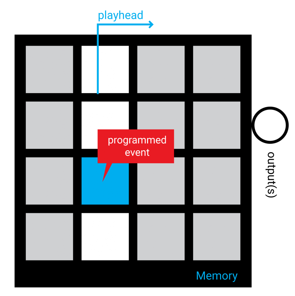
Figure 11: representation of a mono-sequencer
A basic simulated environment for modular elements was programmed using javascript. It defines a graphical user interface, and a module that can be instanced multiple times, which gets graphically represented in the mentioned interface. It contains a layer on top that defines behaviours such as interaction, response to messages and user defined behaviour options. The Fig. 12 is a snapshot of this javascript prototype.
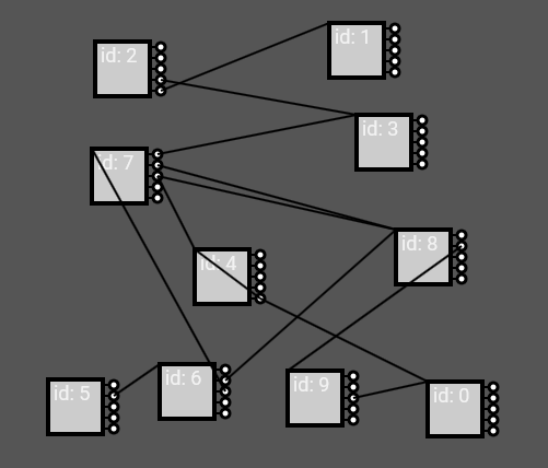
Figure 12: snapshot of the experimentation modular environment
The first exploration led to the idea of using a sequencer as an event-to-event mapping matrix. The first prototype of a mono-sequencer treated the horizontal axis as a time axis, and the vertical axis as different voices, making it a 4 voice, 4 steps sequencer. First, these responded sequentially to a global clock, and in a second attempt, their play head would only change in response to signals that would come programmed from a parent sequencer. A clock active setting needed to be added, however: if none of the sequencers is being triggered by a clock or a user input, there would be no original event to propagate in the first place.
This configuration permits a sequencer to be re-purposed as an event re-mapper: if a sequencer sends a [0,1,2,3] sequence, the child sequencer would play as a normal sequencer, but any other sequence such as [3,1,2,1] will cause the child sequencer to play in non-sequential order (as illustrated in Fig. 13). In this way, the lower sequencer matrix becomes a matrix that maps input signals to output signals.
A usage example of this feature would be to create a palette of notes in a scale that are sequenced by the parent sequencer. Or perhaps, a palette of chords. It already presents us with an improvement over the traditional sequencing approach because, if a musician wanted to change the harmony of a melody, instead of needing to reprogram every note on each step, it would be possible to re-map the musical scale by changing one event per tone. This approach also allows complete transformations to a melody, if for example the user starts mapping all the child sequencer events to a same note, while the parent sequencer is playing a sequence with many distinct notes, and then start adding tonal variations, thus obtaining a melodic progression which was not possible before in most digital sequencers.
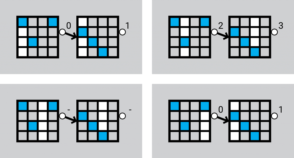
Figure 13: example: the sequence 0,1,2,3 is being remapped to 0,2,-,0, and then to 1,3,-,1
Each possible sequencer value (vertical axis) of these sequencers corresponded to a different output node. This permitted the route of an event to change from one path to another depending on the step: an effect similar to what can be done by using more than one analogue sequencers, if they have dedicated step outputs (such as the Korg sq-10).
Each of these sequencers has an id number that corresponds to the order at which sequencer was created. An interesting emerging problem is that some behaviours may be different depending whether the connection goes against the order of the id numbers or with the order of the id numbers. To exemplify: if sequencer n°2 is parent of sequencer n°1 is against the id order, and the inverse order of connection would be with the id order. This is because the id also dictates the order at which each sequencer’s internal functions are processed by the computer’s processor. If each module is set to respond instantly to any signal, there is no big difference on the response regardless of whether the connection goes up or down the id. Only makes difference with respect to what output number each child is connected to similar to Pure-Data (Puckette 2006, 212). But if the modules are set to wait for a clock step to respond, there will be a difference: if a connection goes up the id number, upon clock tick, the module will have already received the signal to which it has to respond at clock time. If the connection goes down an id when the clock ticks, however, the parent would have not yet sent the signal to which the sequencer has to respond, and therefore, it will not respond until the next clock tick, adding a delay. This problem resembles the one of digital systems design, and is the reason why a processor that has millions of transistors, cannot make more than one sequential operation per clock tick (Vahid 2007), which is contrasted by how a sound signal can go through a full analogue process at virtually the same speed electricity travels across the wire, as seen in field programmable gate arrays.
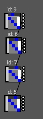
Figure 14: a. a — instant response generates a negligible time difference regarding response up and down id’s.
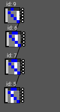
b — When elements are clock bound, down-id connected elements will be one clock behind.
This is an interesting problem for which a solution is needed: if this was a hardware situation, there would be no clear rule, because the elements would not be updated progressively as in the computer simulation. The result is that instead of a clear timing rule, whether the response is delayed or not will depend on the tiny difference of time each processor takes to receive and respond to a signal.
The first proposition that was tried, consists in that a module, although receives and reacts instantly to all incoming signals, it buffers all the resulting signals into an output buffer, is set to be sent in the next clock tick. The second attempted solution consisted on processing all the elements in two separate processes, in the same a software would treat the drawing of graphic layers if it wanted to ensure that elements to be drawn from an array, would be drawn in a different order than the one specified by the array. The problem that emerges from applying the first solution, is that the delay still happens, but in an even less intuitive way: the delayed reaction that is caused by sending a signal to a module with lower id number is relegated to that child module, making the cause of the phenomenon less understandable. A similar behaviour results when trying using the same type of buffer for the inputs instead of the outputs. The second solution idea was applied by giving to each element two signal queues: one queue for the incoming messages, and other queue for the outgoing messages. Upon clock, all outgoing messages are sent, and after clock, all incoming messages are processed, thus generating a new set of outgoing messages, effectively generating a layering of time. This approach generated a consistent behaviour of delaying the signal propagation 1 clock per connection, as seen in Fig. 15.
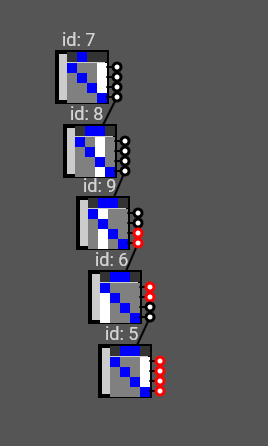
Figure 15: Demonstration of a consistently delayed signal by one clock per connection
The second solution mentioned, however, comprises adding a whole clock delay for each node. This compromise reflects that the system needs not to be intended as globally clock synced except for some modules that are clock-based, such as a sequencer. In a modular system whose modules may need to be coordinated to a clock signal, to be two distinct types of processes need to coexist: the processes which accumulate tasks until the next clock tick, and the processes which respond instantly, regardless of the clock. In this way, it must be expected that signals flowing from one clocked device to another, will obtain a delay in a way analogous to micro-controllers. Signals going through a non-clocked path, on the other hand, get processed as soon as possible, in a way which is analogous to a field programmable gate array.
There are some other clear interesting features that suggest lines for further development. For instance, by extending the capability of each of these mono-sequencers to a complete sequencer, many other expressive manipulations would be possible than the ones offered by isolated sequencers. One example is that the signal emitted from one sequencer to another could be comprised of many numbers (in this exploration the communications were limited to single numbers) in such a way that a static message could be transmitted and routed through many sequencers. In these polyphonic devices, some bytes could be intended as destination messages which dictate how to route and transform the message, while some payload bytes may go through the whole patch sometimes altered and sometimes forwarded until a destination (e.g., synthesizer). This will provide with a concept of multi-layered message processing: one layer which determines the physical route taken by a message, and other layers that determine the effect of this message once it arrives to the final destination. In this way one could use these as modules as if they expanded a single sequencing interface1, and still be able work with them as modules that expand the capability of the system, as in modular environments.
4.3.2 Finding the primary elements of the environment
For the design of an environment, it seems impossible to define the perfect specifications because it is unknown what the future elements, or building blocks will require from the environment to be possible. Poor definitions of an environment could lead to excessive compromises in versatility, and may disallow the existence of certain components. For this, a particular iterative method was devised. This method allows to discover the desired basic building blocks for any given environment that aims to afford the creation of a certain set of systems, and by consequence, define some generic characteristics of the environment which host these building blocks. The use of this process led to a good set of specifications that proved useful for the environment being sought.
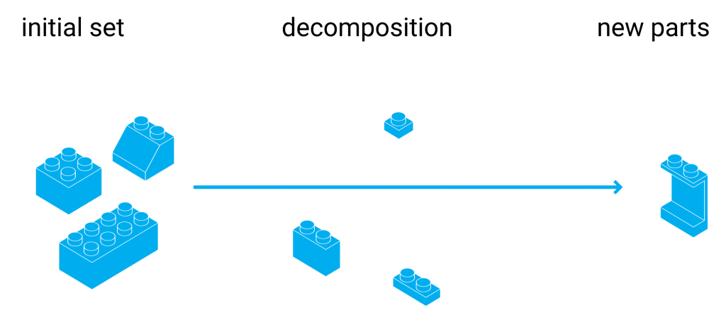
Given an initial set of systems that the environment is supposed to enable, the method allows to break down these system into increasingly basic sub-units until left with a minimal set of different units. It is expected that the resulting parts can be used build any of the initial systems on the set. An example: if the objective is to make a system of parts and pieces that could be used to build any transportation machine, an initial set of systems would be a set of transportation machines. To make this process iterative, the initial set of systems are not considered any more like systems, but like units, which can be potentially made of other sub-units.
The first step is to conceptually explode the current components, into sub-components that permit building easily any of the initial components (e.g., motors, wheels). This is what appears in Fig. 16 as the divide transition between components and sub components. If this was the only step to be iterated, it would lead to a set of sub components that can effectively build any of the initial set of components, but probably many those components will be compatible with one and only one of the initial components. This is why the second step consists on finding similarities among those sub-components: one sub component may be adapted to comply the same function as two-sub components, thus reducing the amount of components and making each sub-component more general-purpose. This also leads to a standardization in the way the components connect one to another, which leads to a third necessary step: homogenizing the ways to bind or connect those components together. The third step could be thought as part of the second step in the sense that communication routines can also be considered sub-components. This is seen in Fig. 16, in the arrow that points down from the sub components. Each iteration consists on taking the sub-components as the new components, and repeating the process, as expressed in the remaining arrow of Fig. 16. Doing this process for enough iterations lead to a certain set of general-purpose components, and hopefully very few components that are specific. The interesting part is that using the general-purpose components that result from the operation, new components can be built that extend the possibilities of the initial set (Figs. 17, 18).
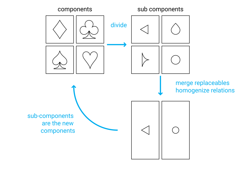
Figure 16: graph of the iterative process

Figure 17: Example of emerging components

Figure 18: Additional example of emerging components
It must be understood that this process can alter the characteristics of the initial set of components, when they are built back from the resulting base components. This depends upon what parts of the final components are required to remain. Following the example of the transportation systems, the smaller set of resulting pieces, can only be achieved by overlooking factors such as appearance and energy-efficiency of the resulting transportation machines. The same phenomenon is exemplified with the playing card graphic icons in Fig. 19.
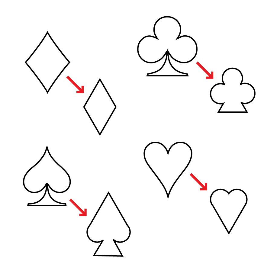
Figure 19: Example of changes in the initial components after the operation
Another caveat to the process, is that each component could have user-defined properties which change properties of the object. In this way, the process can be cheated in a way that the result is just a single component that has so many configuration options, that it can cover any functionality. In the example of the transportation systems set, it would be like defining a block of metal as the base component, because it can be machined and moulded in any way to generate different components. Here the designer’s common sense must take a stance on how adaptable each component needs to be, according to the desired context of application. For some cases it does make sense that a component changes role by using a user-defined parameter: for example a bolt-nut component has the user parameter of how many turns to screw a bolt, which is a perfectly reasonable user-defined parameter, while allowing a wide gamut of configurations. For the current case of musical system design with an eventual application to physical units that integrate many of these components, there is a limit on tweak-ability, and the scripts that define their behaviours should be simple, and as monolithic as possible avoiding an excess of user input interfaces, or switch statements, for example.
The idea of molecular composition, as introduced in the Brocs and Licog explorations, was an interesting starting point, although they needed to be re-defined in many aspects for the purpose of this project. It is worth exploring an environment for molecular composition, based on the idea that an environment that can handle the musical molecules will also be able to sustain any other, more complex modules. Additionally, the molecular paradigms explored in the aforementioned experiences were very limited in terms that the environment was specified only for global musical events, meaning that resulting musical events could not be altered once emitted, but would take effect instantly, as if each component of a composition would have its own speaker. A different environment logic is required to build a modular environment with endless possibilities in the same fashion as a modular synthesizer, thus allowing divergence. Specifically, the best way to re-define the molecular environment would be to proceed with a buildification process using as the initial set of components a mono-sequencer, an event-mapper, an arpeggiator and a Licog.
With respect to the communication protocol, if there is anything quaint on the way that a device is triggered, or about what a device outputs, it would compromise the versatility and compatibility of future devices. A good illustration, as always, is the Lego building block. By good luck or by a good decision, Lego has been able to keep innovating and creating new pieces, and allowing the user to build a very wide range of things, while still keeping compatibility with their earliest pieces. This quality depends on that very first design of the mechanical joint that the first Lego block had. To apply the buildification process in this prototype, a new modular environment was simulated in javascript. To this environment, a sequencer and a Licog modules where programmed and instanced in a way that it was possible to use them in connection. For each of the simulated components, its procedures were analysed as features or sub-components, in order to merge or split them into different functional units, or modules. According to the explained buildification process, the intention is to have the minimum possible amount of different components that would allow building the maximum amount of the initial set of components. It was expected that from exploding these two components, it would later be possible to build other types of systems such as arpeggiators, harmonizers, event mappers and so on.
To encourage modularity as suggested in the last exploration a global clock was not any longer used (Fig. 20, a). This out-ruled the Licog modules as they relied on the global clock. However, this opens the question of how clock-bound (e.g., a sequencer) modules could be triggered in an environment that is exclusively modular. In Pure-Data environment, any signal that is sent also serves as a bang which determines when to propagate the messages. This leads to a frequent need for modules to have several different outputs and specific operations. If there is a need for a module to wait for a clock signal in order to propagate, a specially dedicated module or additional inputs on each module would be needed (Fig. 20, b). As the intention was to homogenize the pieces and communication methods to the minimum, it was defined that instead, a message contains a header number which can be interpreted by each module depending on the module’s functions. In this way, the distribution of the clocks becomes modular, with no requirement for a global clock bus. This allowed the existence of clock messages as distinct from musical event-messages, and therefore the connection between modules can be reduced to as low as one input and one output, while still allowing several functions (Fig. 20, c).
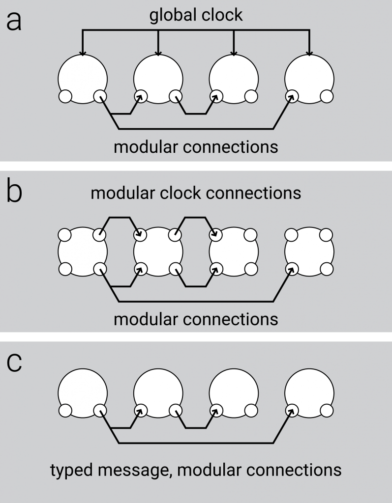
Figure 20: Three approaches to distribute a clock signal in a network of musical devices
This idea was later reinforced by the modelling of a FIFO module, which also needed distinct functions of store message and send buffer messages. If the functions were indistinct, it would not be possible to delay messages as it is required to make a counter, and to make a Licog module.
Given that the messages are typed and not dependent of an input, the clock message becomes a generic trigger message or bang which could have been originated in any other way. More interestingly, it would be possible for modules to manipulate a trigger signal into other type of signal by simply altering its values. A simple module was devised which would record any received message, except for a clock message. If a clock message is received, the currently recorded message would be propagated to the next modules. This facilitates the creation of memory and delayed triggers. This module later derived into a module which could hold any number of event-messages that could be triggered sequentially, in a first in first out (FIFO) fashion.
One of the most obvious modules, which was modelled at the beginning of the experimentation was a module that could send a digital signal to all of its outputs, once it received any signal on its input. After the idea that clock signals were mere messages that were interpreted as clocks by a module, it was defined that this signal generator module could actually be a signal modification module. This module could transform a trigger event-message into a musical event-message or any other. The module effectively operates one input signal for it to become another output signal. This module also could perform conditional operations as to define whether the message is propagated or not upon conditions.
One module that emerged and disappeared during the process was a multiplexer module. It was designed to send an incoming signal only to the output that is indicated in the signal itself. The utility of this module was replaced by the ability of operator modules to have conditional functions: by using many operators, it was possible to build the multiplexer.
During this process, most messages consisted of three bytes, making it potentially MIDI compatible. Two, however, were enough for the extent of this exploration: one number to select a function, and other number to set a value. Any additional numbers would serve to specify more in detail a theoretical note trigger. This led to the additional idea that messages could be of variable length, in which case the header could also integrate the definition of this length.
It was concluded that four modules could describe a wide range of composition elements such as a sequencer, an arpeggiator, a Licog element, and a harmonizer, between others.
- Input module: it converts any defined input into event-messages. its only parameter so far defines which stimuli triggers a bang. In the javascript prototype, so far, can only be either a clock pulse or the press of the space key. In a physical prototype it will probably be able to respond to hardware changes, and to any incoming MIDI or message signal.
- operator module: it performs one operation for each byte of the message. The operations can be arithmetic (e.g., adding one to the second byte of the incoming message) or boolean (e.g., propagate if a condition is true), making it effectively an input filter (e.g., the message passes only if the first byte is 0x80). The operator calculates and propagates the input as soon as received.
- FIFO module: this module stores incoming bytes in an array, if the byte header | 0xF0 equals 0x20, and sends + deletes the oldest byte of the byte header | 0xF0 equals 0x00. There are many other possible headers that may be implementing such as getting the message without removal, getting all the messages, getting the newest message or getting a specific message by index.
- Output module: converts bangs into output. Depending on the context, the output module may send a MIDI signal, trigger a CV, turn a light on or trigger a solenoid.
- These modules would share a common, simple language of a string of integers where:
- first byte defines the function of the message and each module has a different set of reactions for each message header.
- There is a specific header for longer messages, and if the message has this header, the component must wait for a closure byte to stop reading the message. In such case, an escape character needs to be defined which takes effect in the context of long messages, so that sending any byte remains possible.
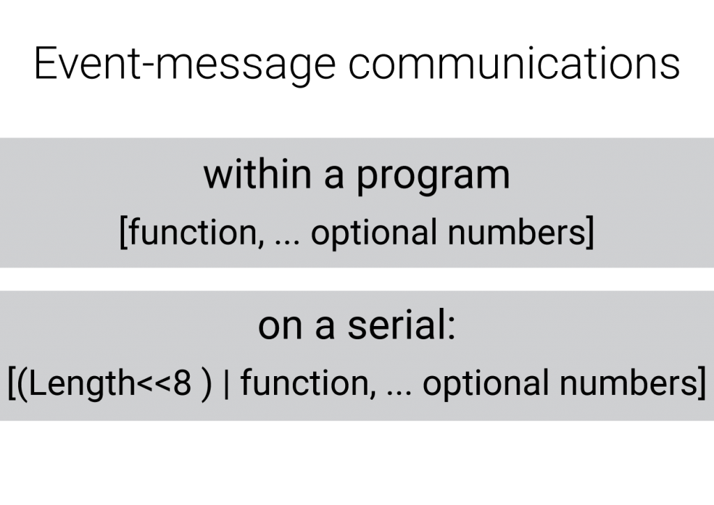
specification of event-messages
This current idea of composition elements becomes similar to the implementation of Pure-Data, were modules can exchange discrete information, but in this case leaving away the continuous variables that Pure-Data handles such as audio buffers. This idea of getting a sub set of elements from the Pure-Data composition environment relates this project to Liam Goodcare’s context sequencer (Goodacre 2018), which builds higher-level components by using Pure-Data. In this process, however the intention is to generate an environment which is dedicated to live composition, which includes the patching of modules through a physical interface.
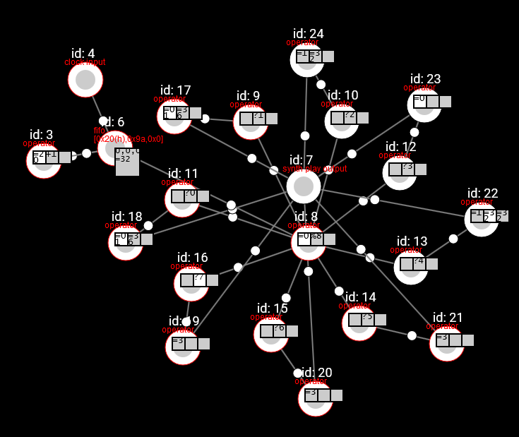
Figure 21: 16 steps sequencer
The Fig. 21 above shows how a 16 step sequencer can be made out of these components. Licog units are also easy to implement with these modules, as a signal can be stored in a FIFO until next clock, and send all messages in FIFO on every clock to the next Licog. It is also possible to build simple arpeggiators, scale mappers, and so forth. This definition of basic modules satisfactorily covers the domain required domain, although the definition of notes-off and control messages remain as an interesting future exploration.
Despite the idea of creating a set of hardware micro-operators that replicate this environment is very interesting, as a project it will be necessary to focus on more complex, and more user friendly ideas of a module. Modules built upon these modules are not easy to manoeuvre as the built entity: a built sequencer, for instance, would not be user friendly as presented in the picture, since changing the sequence length involves changing the structure of the system. It is also interesting to note, that given a definition of the environment that specifies the role of a module and the roles and characteristics of the messages, future modules can also contain aberrations of the resulting basic units, without compromising the compatibility with the rest of the environment, as long as the inputs and the outputs belong to the same specification.
Bibliography
Aldunate Infante, Joaquín. 2013a. “Brocs.” Autotel.co. January. http://autotel.co/portfolio/brocs/.
———. 2013b. “Brocs: Objeto Para Experienciar Sin Conocimiento, La Música de Forma Auto-Télica.” Universidad Diego Portales. https://drive.google.com/file/d/0B_0eojMydbGZcVFuVDJkMVRDb2c/view.
———. 2014. “Licog Composer.” Autotel.co. January 1. http://autotel.co/portfolio/licog-composer/.
Goodacre, Liam. 2018. “Context Sequencer.” Accessed June 26. https://contextsequencer.wordpress.com/.
Puckette, Miller. 2006. The Theory and Technique of Electronic Music. World Scientific Publishing Co. Pte. Ltd. http://msp.ucsd.edu/techniques/v0.11/book.pdf.
Vahid, Frank. 2007. Digital Design. Wiley cop.