Using OpenSCAD
OpenSCAD is a freeware that you can use to make 3D models from lines of code. It is good for parametric design, but as you may guess, it is not so intuitive to use. As far as I know, it neither is good with organic shapes (A curious fact: the Utah teapot) but rather works well with orthogonal shapes. I have dared for the first time to use OpenSCAD. I previously did some tiny attempts, with no major success. The code very easily became clumsy. The notes that I will present can help an incoming user to take a comfortable approach into it:
You want it parametric
OpenSCAD is a good idea because, as any programming language lets you do everything based in variables. In this project I am making a solenoid holder, and by making it in OpenSCAD, I now can adapt it for any solenoid by only changing the variable names. But actually putting variables instead of fixed numbers not only makes your design more versatile, it is also easier to program the shapes this way.
Useful parameters
My project had to fit a solenoid, and it's size will be based on this; this is why my first parameters were all references to the solenoid size.
//units: mm
fitOffset=0.25;
fitOffset2=fitOffset\*2;

coilDiameter=10;
coilD=16.4;

topCapW=11;
topCapH=10;
topCapD=1.5;

topCuelloDiameter=5;

coilBoxD=coilD+topCapD;

columnD=18;
columnDiameter=4;
columnHeadDiameter=5;
columnHeadD=1.35;
A very clear problem you can run into with this, is really knowing what each variable means in respect to the real object. For example, the variables whose names start with topCap, are for a black box in the top of the solenoid cylinder. Which letter represents which real-world axis, and also is this box part of the whole solenoid height, or does it add to it? You totally need to make a reference drawing, to specify what does each variable mean.
The following variables were some that don't have anything to do with the solenoid, but determine rules for some details. I think that these are useful for any project.
//how much the plastic runner/column slides out of the body
pColumnOutbound=5;
//and how much it slides into the coil
pColumnInbound=1.4;
columnRestDistance=8;
//how high is the solenoid holder out of the box
holderAmount=1.2;
//when boolean operation creates interfering faces, offset a tiny bit to overlap bodies
tinyBit=0.01;
tinyBit2=tinyBit\*2;
//how much body to create around hollow
bodyWidth=1.2;
bodyWidth2=bodyWidth\*2;
So, two variables (starting with pColumn) define a movement range, of the metal column that moves inside the solenoid coil. The holder amout defines how "hard" it will be to put the solenoid inside the holder, as it relies on flexing the plastic. Too little, and the solenoid will fall; too much, and is impossible to insert the solenoid in the holder.
The interesting variables here are tinyBit and bodyWidth. Tinybit is a small number that you can refer to when something needs to be almost zero displaced. I'll explain myself better: Imagine that you want to make a hollow tube:
difference(){
    cylinder(d=100,h=100);
    cylinder(d=90,h=100);
}
in this substraction, both faces of the inner and the outer cylinder ar in the exact same place. What happens is that the cylinder will have this interfering face, which I don't know how ugly could result if printed. 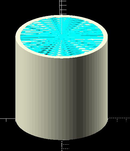 So, in this project, to avoid this I added two tinyBits plus to the cylinder height, and translated it another tinybit down in Z, to avoid this interference in the bottom aswell. This approach is a bit hacky; but worked well for my purpose of the solenoid holder.
Deconfusing rotation
It is usually hard to think three-dimensionally, and even harder if you have to do 3d rotations. In OpenSCAD, objects are most easily build along the Z-axis, having their profile in the X/Y plane. For example, the cylinder default is to look like a circle from above, and all the coordinates of objects will first be X, then Y, and then Z. I found very helpful to build the model in an odd rotation, giving preference to the default.
In terms, this is very hard to model:
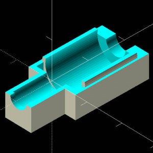
While this is pretty easy:
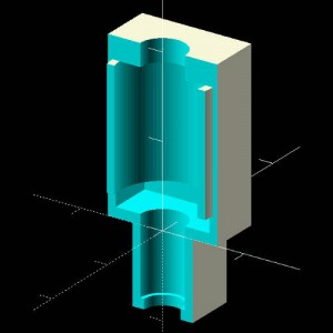
The difference is only position and orientation. The easiest one to model has most of the cilinders centered in the x:0, y:0, and they are extruded along the z axis. If you go by rotating each individual cylinder to obtain the model as in the first image, it will get confusing very easily. I just designed the model in the easy position, and then rotated it entirely to my wanted position.
The model
My solenoid holder code is still pretty clumsy. Apart from needing some practice, there are more tools to OpenSCAD than the ones I used, that would make the model better looking and the code better organized. It goes as follows:
/\*
Solenoid holder, Joaquin Aldunate
http://autotel.co
\*/

//render quality
$fn=80;
//units: mm
//how much space to leave for objects to fit. The 3d printer makes the objects a bit bigger than the design due to the filament's width.
fitOffset=0.25;
fitOffset2=fitOffset\*2;

coilDiameter=10;
coilD=16.4;

topCapW=11;
topCapH=10;
topCapD=1.5;

topCuelloDiameter=5;

coilBoxD=coilD+topCapD;

columnD=18;
columnDiameter=4;
columnHeadDiameter=5;
columnHeadD=1.35;

//how much the plastic runner/column goes out of the body
pColumnOutbound=5;
//and how much it goes into the coil
pColumnInbound=1.4;
//how high is the solenoid holder out of the box
holderAmount=1.2;
//when boolean operation creates interfering faces, offset a tiny bit to overlap bodies
tinyBit=0.01;
tinyBit2=tinyBit\*2;
//how much body to create around hollow
bodyWidth=1.2;
bodyWidth2=bodyWidth\*2;

columnRestDistance=8;

//it is easier to think of the cubes in the same way as square cylinders. This function does that
module prismaCube(W,H,D){
    translate(\[0,0,D/2\]){
        cube(\[W,H,D\],center=true);
    }
}
bottomExtent=(columnRestDistance+columnHeadD);

union(){
    rotate(\[-90,0,0\]){
        difference(){
            union(){
                prismaCube(topCapW+bodyWidth2,topCapH+bodyWidth2,coilBoxD+bodyWidth2);
                translate(\[0,0,-bottomExtent\]){
                    prismaCube(columnHeadDiameter+bodyWidth2,topCapH+bodyWidth2,bottomExtent);
                }
            }
            //cutout half of the container
            union(){
                translate(\[-100,-200,-tinyBit\]){
                    cube(200,100,100);
                }
                translate(\[-100,-200-columnDiameter/2-bodyWidth,-100\]){
 cube(200,200,200);
                }
            }
            translate(\[0,0,bodyWidth\]){
                union(){
                    //sustraction of the solenoid shape
                    cylinder(d=coilDiameter+fitOffset2, h=coilD);
                    prismaCube(topCapW+fitOffset2,topCapH+fitOffset2,topCapD+fitOffset2);
                    //adding the part that holds the plastic runner/column
                    translate(\[0,0,-bottomExtent\]){
                        cylinder(d=topCuelloDiameter+fitOffset2, h=100);
                        translate(\[0,0,-bodyWidth-tinyBit\]){
                            cylinder(d=columnDiameter+fitOffset2, h=100);
                        }
                    }
                }
            }
        }
    }

    //make holder
    difference(){
        rotate(\[-90,0,0\]){
            translate(\[0,0,bodyWidth+topCapD+fitOffset2\]){
                difference(){
                    cylinder(d=coilDiameter+fitOffset2+bodyWidth\*1.5, h=coilD-fitOffset2-topCapD+tinyBit);
                    translate(\[0,0,-tinyBit\]){
                        cylinder(d=coilDiameter+fitOffset2, h=coilD-fitOffset2+tinyBit2);
                    }
                 }
            }
        }
        translate(\[0,0,holderAmount\]){
            prismaCube(100,100,100);
        }
    }
}

//make sliding plastic column
rotate(\[-90,0,0\]){
    union(){
        //sustraction of the solenoid shape
        //adding the part that holds the plastic runner/column
        translate(\[0,0,-bottomExtent\]){

            translate(\[0,0,fitOffset+bodyWidth\]){
                cylinder(d=topCuelloDiameter-fitOffset2, h=columnHeadD);

            }
            translate(\[0,0,-pColumnOutbound\]){
                cylinder(d=columnDiameter-fitOffset2, h=bottomExtent+bodyWidth+pColumnOutbound+pColumnInbound);
            }
        }
    }
}