How to make a mechanic synth
From solenoids to fun
This is one of my first tutorials and may have a lot to be improved; so I appreciate all the questions and comments.
What is a mechanic synth?
The idea of the mechanic synth is to simulate the function of a mainstream synth, but with a mechanic output. The mechanic synth takes MIDI for input, and triggers motors and solenoids according to these. Being MIDI means, you can plug it to your computer by using a serial to midi bridge or with some modifications, to pretty any synth that has a MIDI output, and use it trough it.
Just building it
The wiring
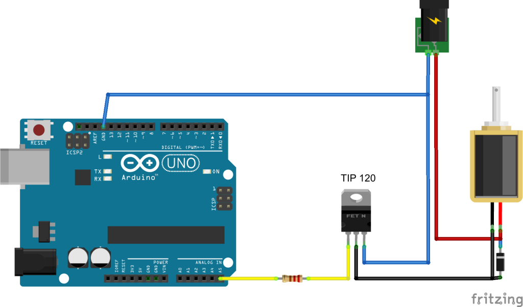
So we want the Arduino to control the solenoids. It won't work if you plug the solenoids directly in the Arduino. For each solenoid you will also need a 2.2k resistor and a TIP 120 transistor. Here is the schematic to plug only one solenoid to the Arduino:

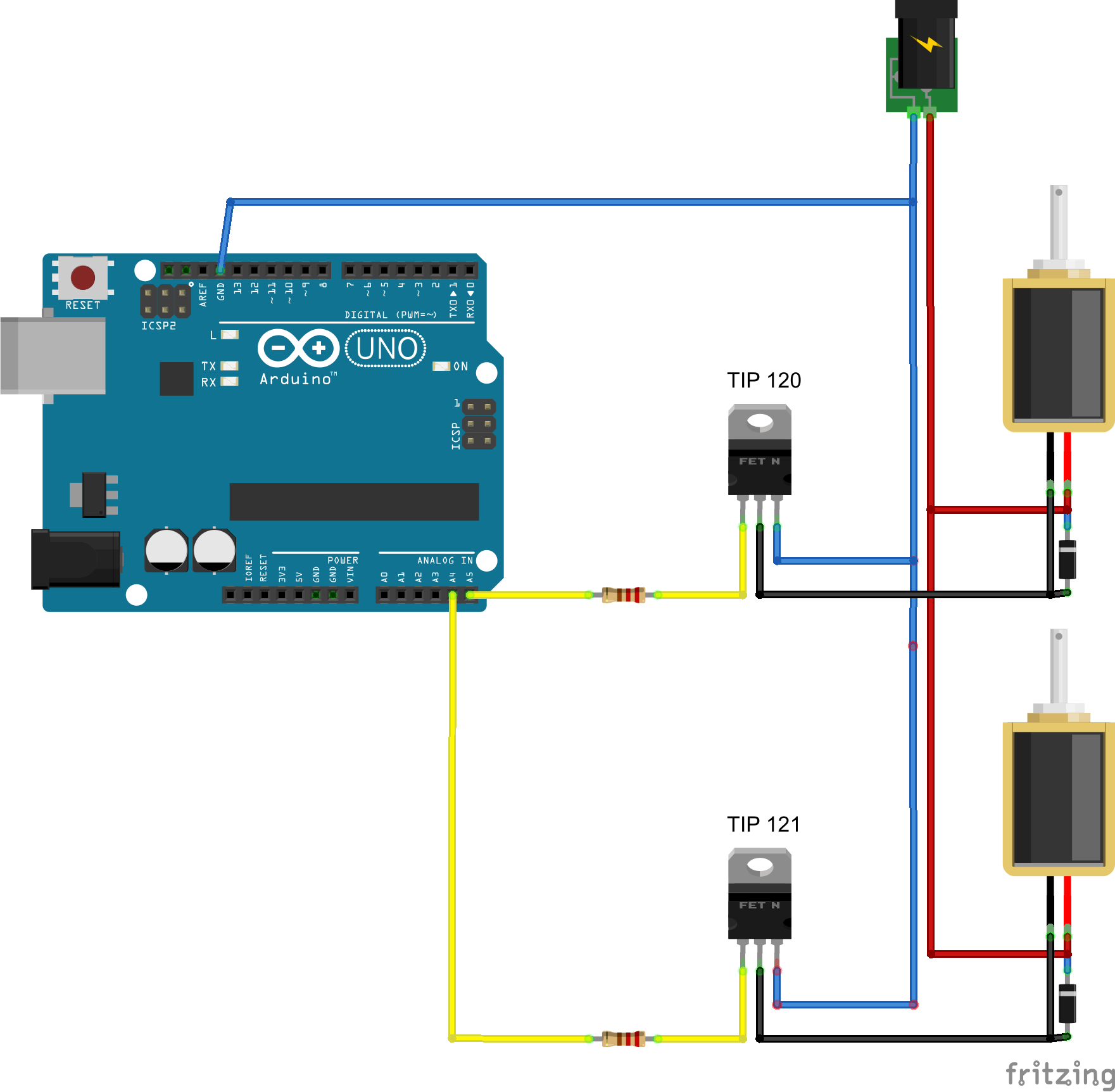
And you add more solenoids like this:
Funnily at the end of this video you will b suggested other videos of the same thing; that will be probably better explained, if you couldn't follow.
I recommend to use a regulated and secure power supply. Be aware that wall power is deadly; and you shouldn't work with it unless you know what you are doing very well. If you want to power the Arduino and the solenoids with the same supply; is explained below.
Arduino sketch
Burn this sketch in your arduino. If you don't know how to do this, I recommend the Arduino blink tutorial
unsigned int beatlong = 0x00FF;

unsigned long currentloop=beatlong;
int pinTimers \[\] = {
  0, 0, 0, 0, 0, 0, 0, 0
};
unsigned int pinDurations \[\] = {
  200,
  200,
  200,
  200,
  200,
  200,
  200,
  200
};
int pins \[\] = {
  A0, A1, A2, A3, A4, A5, 9, 10
};
int pinAmount = 8;
void setup() {
  Serial.begin(31250);
  for (int a = 0; a < pinAmount; a++) {
    pinMode(pins\[a\], OUTPUT);
    digitalWrite(pins\[a\], HIGH);
    delay(20);
    digitalWrite(pins\[a\], LOW);
    delay(150);
  }
  Serial.write(0xFA);
}
void loop() {
  if (currentloop > 0) {
    currentloop--;
  }
  else {
    Serial.write(0xF8);
    currentloop = beatlong;

  }

  pinTimer();
  midiCheck();
}
void midiCheck() {
  unsigned int inByte = 0;
  unsigned int inByte2 = 0;
  unsigned int inByte3 = 0;
  if (Serial.available()>2) {
    inByte = Serial.read();//read first byte
    inByte2 = Serial.read();//read next byte
    inByte3 = Serial.read();//read final byte
    //trig(5, 0, 0);
  }
  switch (inByte) {
    case 0x90:
      trig(0, inByte2, inByte3);
      break;
    case 0x91:
      trig(1, inByte2, inByte3);
      break;
    case 0x92:
      trig(2, inByte2, inByte3);
      break;
    case 0x93:
      trig(3, inByte2, inByte3);
      break;
    case 0x94:
      trig(4, inByte2, inByte3);
      break;
    case 0x95:
      trig(5, inByte2, inByte3);
      break;
    case 0x96:
      trig(6, inByte2, inByte3);
      break;
    case 0x97:
      trig(7, inByte2, inByte3);
    default:
      trig(0, 0, 0);
  }
}
void pinTimer() {
  for (int a = 0; a < pinAmount; a++) {
    if (pinTimers\[a\] == 1) {
      digitalWrite(pins\[a\], LOW);
      pinTimers\[a\]--;
    }
    else if (pinTimers\[a\] > 0) {
      pinTimers\[a\]--;
    }
  }
}
void trig(unsigned int a, unsigned int b, unsigned int c) {
  pinTimers\[a\] = c<<4;//pinDurations\[a\];//c<<4
  digitalWrite(pins\[a\], HIGH);
}
Solenoid holders
I took solenoids from broken radios. If you buy a solenoid, it ill probably have a spring by itself; but if it is of any use, in GrabCad you can find the solenoid holders for two sizes.
Playing it from the computer
You can use your computer to play this, if you know how to generate midi events. I use two programs to connect the Mechanic synth to my DAW: Tobias Erichsen's LoopMidi and the Hairless midi-serial. If you need further help, ask in the comments below.
Play along
So, you can build the mechanic synth and play by programming drum patterns in it, and then changing the different drum elements that it plays. You could use also an external sequencer or the computer to trigger its solenoids, and tweak the sounds by mechanic means (such as pressing the elements that are being stroken, filling a glass with water, touching a metal bar, etc.) I also added to mine, an electronic amplifier and a motor with a gear that frictions a piece of plastic. The sound I most liked was a bent cardboard square.
https://www.youtube.com/watch?v=VoamxHGf3H8
How to hack it
Single power supply for the whole system
You may want the Arduino to run without a computer; and take the power from the same power supply as the solenoids. For this, you can use the VIN Arduino pin. Be very careful with this, because 12 volts is the Arduino tolerance limit; and is super above your USB plug tolerance. There are many mistakes that could fry your Arduino or your USB port, such as plugging the cables in the opposite order.
The electromechanic part
Solenoids and motors are two means of generating movement from electricity. In this sense we can say that a speaker is also a electromechanic device, and that we are actually building different kinds of speakers here. Thing is that opposed to a speaker, with a solenoid, we are not generating only one audio pulse per voltage variation, but several. A complete timbre. Making sounds from solenoids is making purposefully really bad quality speakers. You could also think of this as being pinball components machines. I wonder how many other sounds and features we could borrow from there.
In order to make a solenoid to move weight, it requires more electric power than the power an arduino can handle. If we provide the microcontroller with the whole voltage and current that a solenoid needs, that means instant fry. So how can we control the solenoid by using arduino, but not to power the solenoid with the arduino itself. This is where the TIP12o (TIP122 as well) is useful. For our specific case, the tip 120 controls a high voltage source, based on the level of a low voltage source. We can think of it as an electronic switch button. Following the drawing; when the leftmost foot receives 5v high, it connects the 12V input to the solenoid. I must confess that I understand little about the electronics involved; that is why I took the schematic from a tutorial from martyncurrey.com.
Thankfully the arduino board has a voltage regulator that will cut the supply to protect the chip. I have tried many different connections without yet managing to fry an arduino, but be careful: over the price of an arduino, you can also compromise your computer's USB port. Arduino controlled solenoids schematics. Based on martyncurrey.com
The arduino program explained
The sketch works by constantly listening to the serial, and triggering a pin when it receives a determinate sequence of bytes, in correspondence to the MIDI standard.
see more:
http://www.indiana.edu/~emusic/etext/MIDI/chapter3\_MIDI4.shtml
https://www.nyu.edu/classes/bello/FMT\_files/9\_MIDI\_code.pdf
Let's have a look part by part. The first part, declares variables needed for the whole program and the setup.
unsigned int beatlong = 0x00FF; // MIDI clock interval, to send clock signals from the arduino
unsigned int swing = 0x000F; // Swing, a feature I had no time to implement
unsigned int swingSide = 0;
unsigned int currentloop = 0; //Is a counter. This contains the midi clock current time.
int pinTimers \[\] = {
  0, 0, 0, 0, 0, 0, 0, 0
};//Counters for each pin
unsigned int pinDurations \[\] = {
  200,
  200,
  200,
  200,
  200,
  200,
  200,
  200
};//trigger duration for each pin.
int pins \[\] = {
  A0, A1, A2, A3, A4, A5, 9, 10
};//list of pins to be used to control the solenoids. You can add or change based on what you need
int pinAmount = 8; //Hard coded length of the previous array.
The variables declared in the top are timers used for different needs along the program. Their use will be clearer on the following sections. The pins array gives you the first chance of tweaking the program. They map the Arduino pins to use as control outputs for the solenoids. If you want to use analog inputs, for instance, you could clear all the A pins and change them for the digital pins. The solenoids don't need analog outputs.
void setup() {
  Serial.begin(115200);
  for (int a = 0; a < pinAmount; a++) {
    pinMode(pins\[a\], OUTPUT);
    digitalWrite(pins\[a\], HIGH);
    delay(20);
    digitalWrite(pins\[a\], LOW);
    delay(150);
  }
  Serial.write(0xFA);
}
We setup the serial to communicate either to the computer or to a midi synth. The serial communications happen on the USB and in the pins 0 and 1 of the Arduino as well. Actually the required MIDI baud rate is 31250. I chose 115200 because this works best with the hairless MIDI to serial, but if you want to connect this to a standard MIDI device; you just need to set it back to 31250, and wire the Arduino to the MIDI gear following an Arduino to midi tutorial.
After that, we set each pin from the pins array to output, and make a test of each. Each time the Arduino starts, it will trigger each solenoid.
void loop() {
  if (currentloop > 0) {
    currentloop--;
  }
  else {
    Serial.write(0xF8);
    currentloop = beatlong;

  }

  pinTimer();
  midiCheck();
}
In the loop, we run the midi clock timer. I added the clock functionality to plug my MIDI sequencer, that doesn't run without an external midi clock. This simply counts backwards (currentloop--) until is zero, where it will be set again to beatlong (which was 0xFF) and send a standard MIDI clock signal. 0xF8 is the midi signal that most gear will understand as a midi clock signal.
void midiCheck() {
  unsigned int inByte = 0;
  unsigned int inByte2 = 0;
  unsigned int inByte3 = 0;
  if (Serial.available()>2) {
    inByte = Serial.read();//read first byte
    inByte2 = Serial.read();//read next byte
    inByte3 = Serial.read();//read final byte
    //trig(5, 0, 0);
  }
  switch (inByte) {
    case 0x90:
      trig(0, inByte2, inByte3);
      break;
    case 0x91:
      trig(1, inByte2, inByte3);
      break;
    case 0x92:
      trig(2, inByte2, inByte3);
      break;
    case 0x93:
      trig(3, inByte2, inByte3);
      break;
    case 0x94:
      trig(4, inByte2, inByte3);
      break;
    case 0x95:
      trig(5, inByte2, inByte3);
      break;
    case 0x96:
      trig(6, inByte2, inByte3);
      break;
    case 0x97:
      trig(7, inByte2, inByte3);
    default:
      trig(0, 0, 0);
  }
}
MidiCheck does the job of listening wether there is serial data to read. If so, it locks for the lapse of three bytes and remembers them in the vars inByte, inByte2 and inByte3. When it finishes, it basically does something different depending on the meaning of each byte. For instance, I am only reading note on bytes which start as 0x9_ (0x90,0x91,[...]), and making a specific solenoid trigger depending on that note on byte's channel. Here is where you can map either solenoids to channels, solenoids to notes, to velocities or even make actions for control commands (0xB_). See the midi Message Table
void pinTimer() {
  for (int a = 0; a < pinAmount; a++) {
    if (pinTimers\[a\] == 1) {
      digitalWrite(pins\[a\], LOW);
      pinTimers\[a\]--;
    }
    else if (pinTimers\[a\] > 0) {
      pinTimers\[a\]--;
    }
  }
}
void trig(unsigned int a, unsigned int b, unsigned int c) {
  pinTimers\[a\] = c<<4;//pinDurations\[a\];//c<<4
  digitalWrite(pins\[a\], HIGH);
}
At last, the little secret: the pinTimer. It recieves three values that have correspondance with the three MIDI bytes: channel, note and velocity (a, b and c) and makes the actual voltage change in the Arduino pins. It makes the midiCheck function switch statement to look redundant, but in this way I believe is easier to tweak.
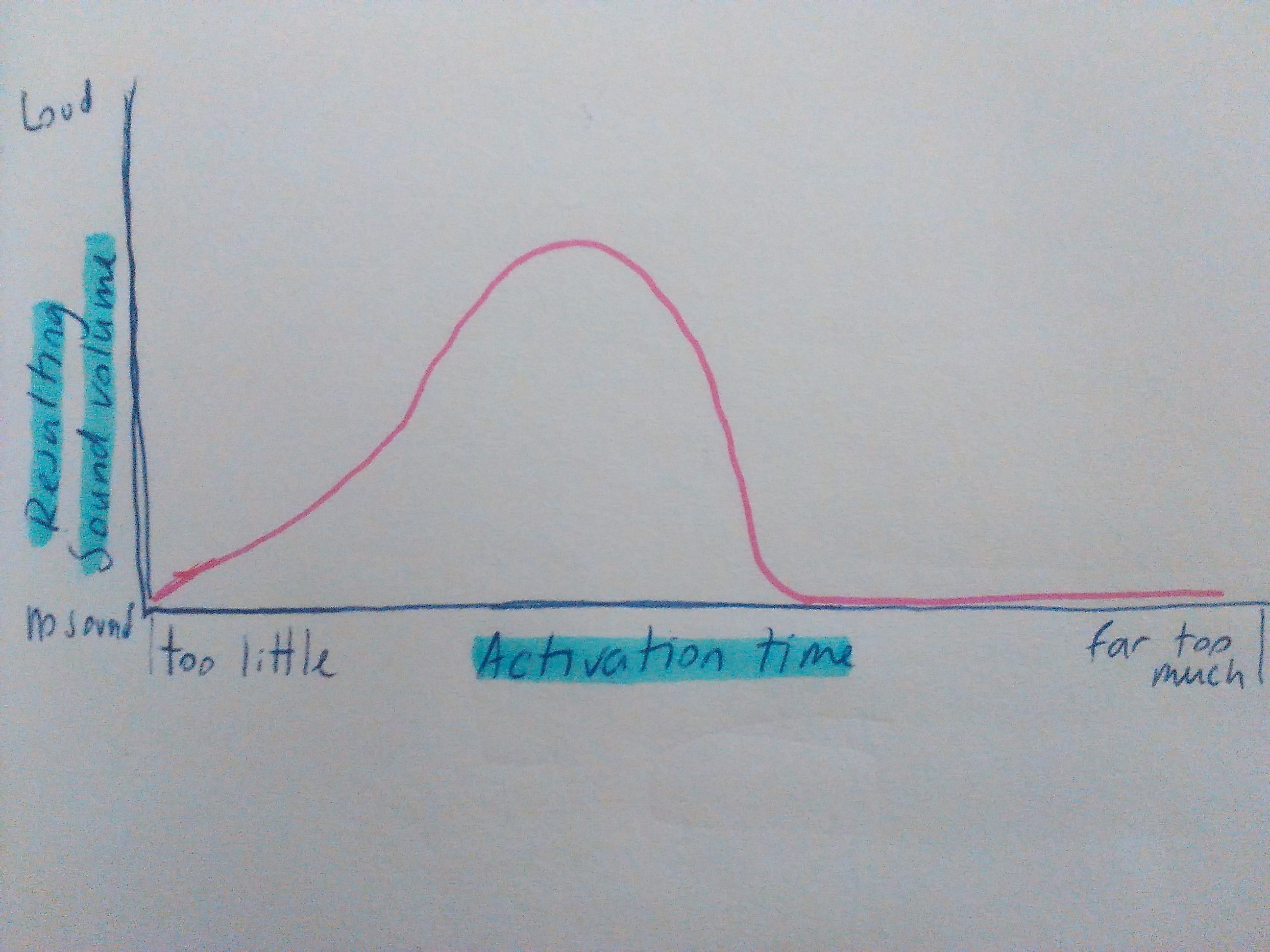
So, we cannot modulate the solenoid movement strength by using the PWM (at least, as far as I know) but, we can modulate this strength by modulating the activation time. If the time is too short, the coil will not move the bar. If the time is too long, the coil will attract and hold the bar. We defined pinDurations at the beginning as 200 cycles, and you can use these fixed velocities by replacing the current c<<4 value, with the commented pinPurations[a]. Currently this duration depends on the MIDI input velocity; and is calculated with the bitshift
c<<4 operator so we can add some expression to the sound. It really makes a difference to play percussion sounds with velocity differences than without.