Polar sound transformations
Inspiration
I had an intuition for the concept of treating sound from a polar perspective. By this I mean sound that changes according to a direction. I did this experiment in JavaScript, and you can find it at the repository: https://github.com/autotel/vectoidal-proof-of-concept. It is not hard to play with it if you want. Please always take care of your audition while playing with these experiments. Very loud sounds can come out and damage your hearing if you are wearing headphones. Make sure to detach them from your ear or use speakers. Also adjust the volume to low, safe levels.
The idea came first to mind while displaying sound grains in a circular fashion. One example of such way to display sound waves is the granular synth concept I did some time ago. In order to display a sound around a center, one must use the polar to Cartesian conversion formulas. The sample's index is taken as theta (2*pi*index/length), and the sample's level as radius. An offset has to be added to radius too. Otherwise the samples appear all crammed in the center, because the audio samples range go from -1 to 1.
({theta,radius})=>{
    return {
        x:(Math.cos(theta)-1)*(radius*level),
        y:(Math.sin(theta)-1)*(radius*level),
    }
}
The use of sine, of course, directly suggests audio. Since it is in a graphical context, one cannot help but think about possible graphical transformations to a sound. One incredible example of such is Fenderson's oscilloscope music. This work is inspired in the audio goniometer's emergent behavior of sometimes displaying nice shapes out of stereo signals. Another artist that took inspiration from this concept is Macumbista, in his vector synthesis work.
In relation to the goniometer-like presentation of sound, I was wondering in which ways the sound can be graphically transformed. I had the intuition of rotating this representation graphically. For a long time this intuition did not make sense in my mind. If I were to rotate this sound, the result would be a mere phase change of the same.
Sound transformations in JS
Javascript's Web audio api is great for these experiments. While it possible to take a high-level approach to sound, it also allows sample-by-sample processing. The well-known drawback of this method, is the speed. Although I am running these scripts in a decent computer, the processing speed is comparable to the one of a microcontroller. This can be partially tackled by implementing web assembly modules for the heavy lifting part. We are not diving into that topic, as this is just a proof of concept. It was just worth mentioning the methods by which we can process samples individually and play them.
const buffer = new AudioBuffer({
    length: this.angles[0].audioArray.length,
    sampleRate: audioContext.sampleRate,
    numberOfChannels: this.angles.length,
});

for(
    let channelNumber = 0;
    channelNumber<this.angles.length;
    channelNumber++
){
    const chanArr=this.angles[channelNumber].audioArray;
    const nowBuffering = buffer.getChannelData(channelNumber);
    for (
        var sampleNumber = 0;
        sampleNumber < chanArr.length;
        sampleNumber++
    ) {
        nowBuffering[sampleNumber] = chanArr[sampleNumber];
    }

}

source = new AudioBufferSourceNode(audioContext, {buffer});
if(!source) throw new Error("failed to make source");

source.connect(myGain);
source.loop = true;
source.start(0);
A personal side note: I wonder what happens if one tries to edit this audio buffer while playing the sound.
The experiment
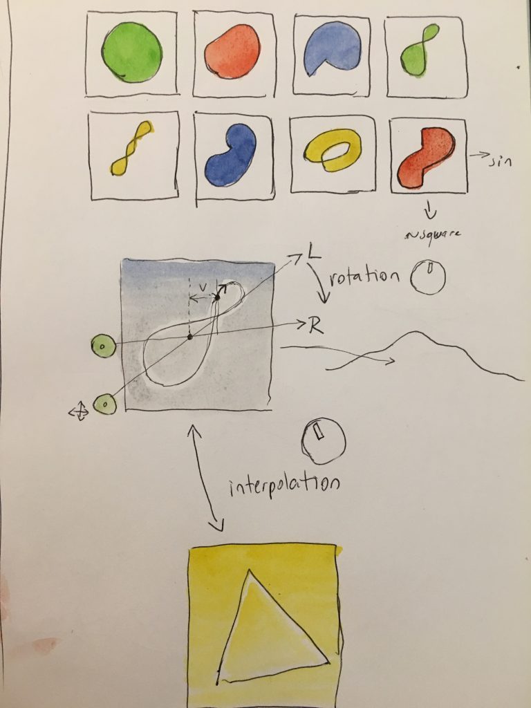
The idea became more interesting when I placed the attention into the "point of view" aspect rotating the sound wave. By these means, a point of view might not have access to certain information. This can be done by viewing the wave as one-dimensional after being rotated. I will proceed to explain this process below.
Rotate and squash
In the previous case we were really projecting the distance of each sample to the center point. By rotation, I mean that the wave is cut in two, and the latter part is prepended to the first part. This results in exactly the same wave, just with a different phase (fig.3).
 * get array starting at the indicated start point,
 * and ending in start-1. Contents are appended in a
 * round buffer fashion
 */
function getArrayAround(start){
    let partA=myAudioArray.slice(0,start);
    let partB=myAudioArray.slice(start,myAudioArray.length);
    return partB.concat(partA);
}
The new transformation consists on projecting the distance between a line and each sample (fig.2), instead of projecting them to a point (fig.3). The first step of changing the phase of the input wave as a way of "rotating it" turned out to be meaningful, but merely projecting the wave to a Cartesian plane and then back as polar coordinates, obviously, caused no changes to the wave.
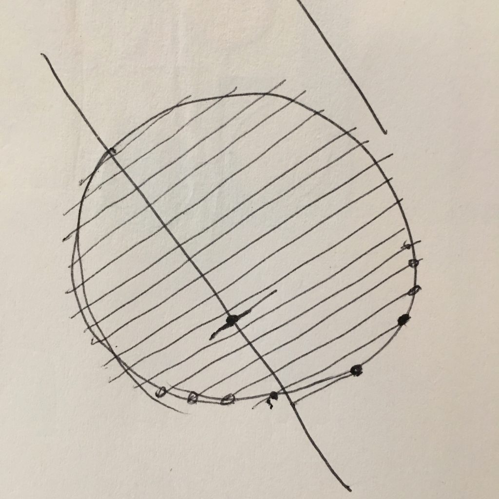
fig.2
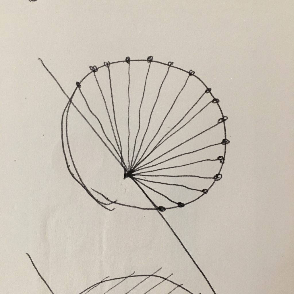
fig.3
Removing a dimension
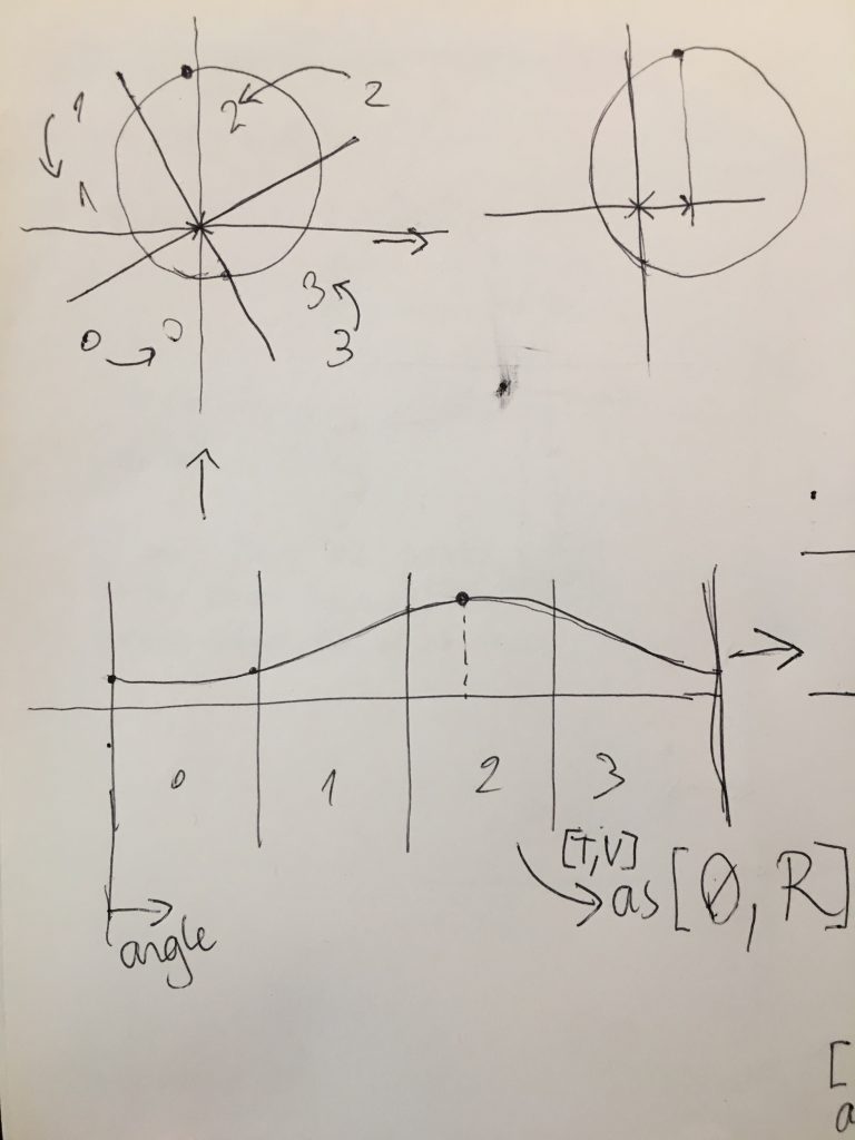
When the wave has been projected in the Cartesian space, as a "circle", one dimension has to be removed in order to produce an interesting change to the wave. In this way, we get the desired point of view from a line, which is one-dimensional, and is effectively the distance from a line to each point. Note that the fig.2, rotated so that the axis becomes horizontal, what we get are just vertical lines. This means that we are only interested in the "y" value of each point. Once the wave has been rotated and projected in the Cartesian plane, projecting the circle to the perspective line is as easy as setting all x's to 0.
/**
 * convert an array of th,r into x,y coords around 0,0
 * @param {{th:number,r:number}[]} arr
 * @param {number?} dcOffset
 * @returns {{x:number,y:number}[]}
 */
export const arrayPolarToCartesian=(arr,dcOffset=0)=>{
    return arr.map(({th,r})=>{
        const rpdc=r+dcOffset;
        return {
            x:Math.cos(th)*rpdc,
            y:Math.sin(th)*rpdc
        }
    });
}
For the computer this is not a step more, but a step less; since we can just omit converting the x component when projecting the polar coordinates to the Cartesian plane. Below the code again, with a bit less work.
/**
 * convert an array of th,r into x,y coords around 0,0.
 * X is not calculated and set to 0
 * @param {{th:number,r:number}[]} arr
 * @param {number?} dcOffset
 * @returns {{x:0,y:number}[]}
 */
export const arrayPolarToCartesianAndSquashX=(arr,dcOffset=0)=>{
    return arr.map(({th,r})=>{
        return {
            x:0,
            y:Math.sin(th)*(r+dcOffset)
        }
    });
}
Adding the point of view of a line to a sound sample, in short, consists on imagining that the sound samples is an array of polar coordinates, where time is the angle (theta) and the level is the radius; projecting those to a Cartesian plane and forgetting one of the axes (x), and then projecting them back to polar. The sample has been transformed!
/**
 * Cartesian to polar converter
 * convert an array of x,y into th,r coords around 0,0
 * @param {{x:number,y:number}[]} arr
 * @param {number?} dcOffset
 * @returns {{th:number,r:number}[]}
 *
 */
export const arrayCartesianToPolar=(arr,dcOffset=0)=>{
    return arr.map(({x,y})=>{
        return{
            r:Math.sign(x+y) * Math.sqrt(x*x+y*y)-dcOffset,
            th:Math.atan2(y,x)
        }
    });
};
Adding a Dc offset variable was a nice additional dimension. Dc offset is added to the wave at the beginning of the process, and subtracted after the process. The resulting wave has the same DC offset as the initial one, but since the wave gets projected different to the Cartesian space, the angle transformation varies according to that offset.
/**
 * takes polar coordinates array, maps them
 * in a cartesian space around 0,0, sets all
 * x to zero in the cartesian space and converts
 * back to polar array.
 * @param {{th:number,r:number}[]} arr
 * @param {number?} dcOffset
 * @returns {{th:number,r:number}[]}
 */
export const arraySquashPolarAxis=(arr,dcOffset=0)=>{
    return arrayCartesianToPolar(
        arrayPolarToCartesianAndSquashX(arr,dcOffset)
    );
}
vectoidal proof of concept, screen capture of the experiment
Future
It is interesting to think about other possible transformations. For instance, what would happen if the center points are changed. To project the polar coordinates to Cartesian, using one center and then using a different center to project them back to polar.
I'm slowly finding out what are the cheapest and most repeatable ways to make stand-alone digital synthesizers. This might be one nice way of modelling sounds. If I feel like it, I might evolve the currently existing example so that it sounds nicer in the browser. Currently rotating the angle causes some audio glitches, but adding a form of sound buffer interpolation would let us play with it as a synth. There needs to be also some form of volume control, because it is really annoying to have a constant sound.