molecular sequencer: choosing a communication protocol
How are the different modules going to communicate with each other?
Context and problem
To make a modular sequencing system, I need to communicate several electronic devices, in such a way that real-time events can propagate fast throughout some, or many modules, while each module produce transformations to these signals. As we are speaking about communications, we will now refer a module (or music performance interface) as node. Nodes are the pseudonym for the units that run a program that lets them participate in the bus, and have the user interaction interface.
Communication between nodes in a network is very complex because of all the factors that are involved. The design and interaction of the product is also compromised in the mode of communication between nodes. As an example, if the network is point to point, then the expected interaction of the user involves patching the modules in the same way as modules are patched in an Eurorack system, mechanically. Otherwise, in a common bus network for instance, the user would be expected to virtually patch modules, as they are all already fully connected from the start.
The main challenge here is to create an algorithm to prevent data collision. Data collision is when two nodes need to send a message at the same time. A bus can't support more than one message at a given time, and a microcontroller can't (or has a limited capacity to) listen to more than one incoming message. This is similar to spoken communications, where we cant listen to more than one person speaking to us at the same time.
The main problems of concern are:
- the achievable data rate, because this determines the amount of interaction that will be possible between units.
- The reliability; which is the ratio of information that is not lost. It should be 1 or very near. Information can get lost mainly because the reception device may be busy, because the message was destroyed due to noise, or because messages from two nodes overlapped in a bus.
- The processing that is required from each unit in the network, because the units need to do other things than only communicate.
Tested networks
point to point
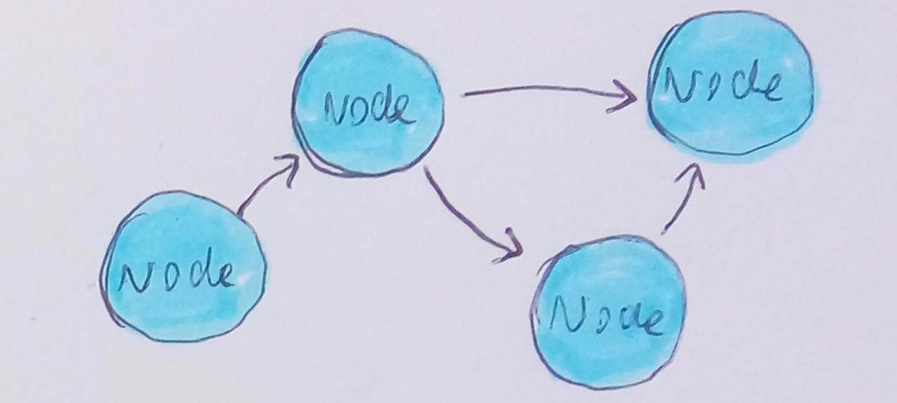 The idea of the point-to-point network is that each node is only aware of those nodes whose inputs are connected to it. Daily life examples of this could be neurons, manufacture and distribution chains, or the postal service. Other example is the software PureData.
With Rs232.
It became unviable in front of the realization that a unit may need to receive signals from more than just one unit, while this protocol is intended for one to one communications only. Albeit the AtMega 2560, has four RS232 pair of pins, it would either constrain the extendability of the protocol or require a lot of hardware implementation. It also has the problem that it would require one dedicated socket for each input or output, limiting these to only four, including the possible MIDI input and output.
Polite Serial
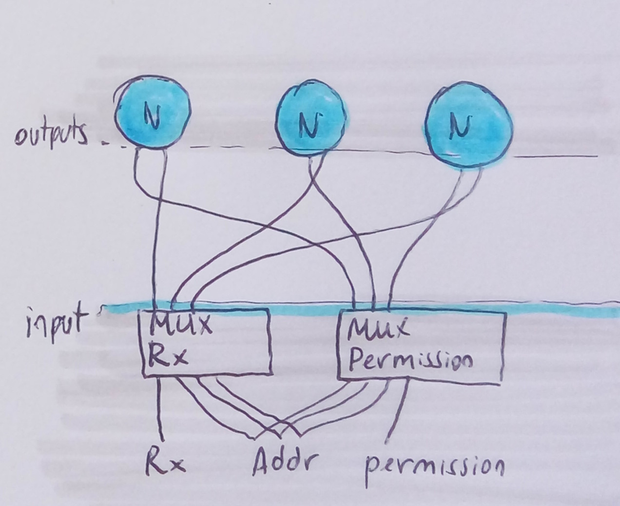
Is an idea of a multiplexed Rs232; where a RX pin would be connected sequentially to different multiplexor pins, theoretically allowing any quantity of outputs to a single port. This idea could theoretically work if the system has other, parallel multiplexor that distributes to the sending devices, an electric flag granting permission to transmit, as a consequence of the multiplexor being connected. I discarded this plan because it appeared another idea that would require less hardware than this.
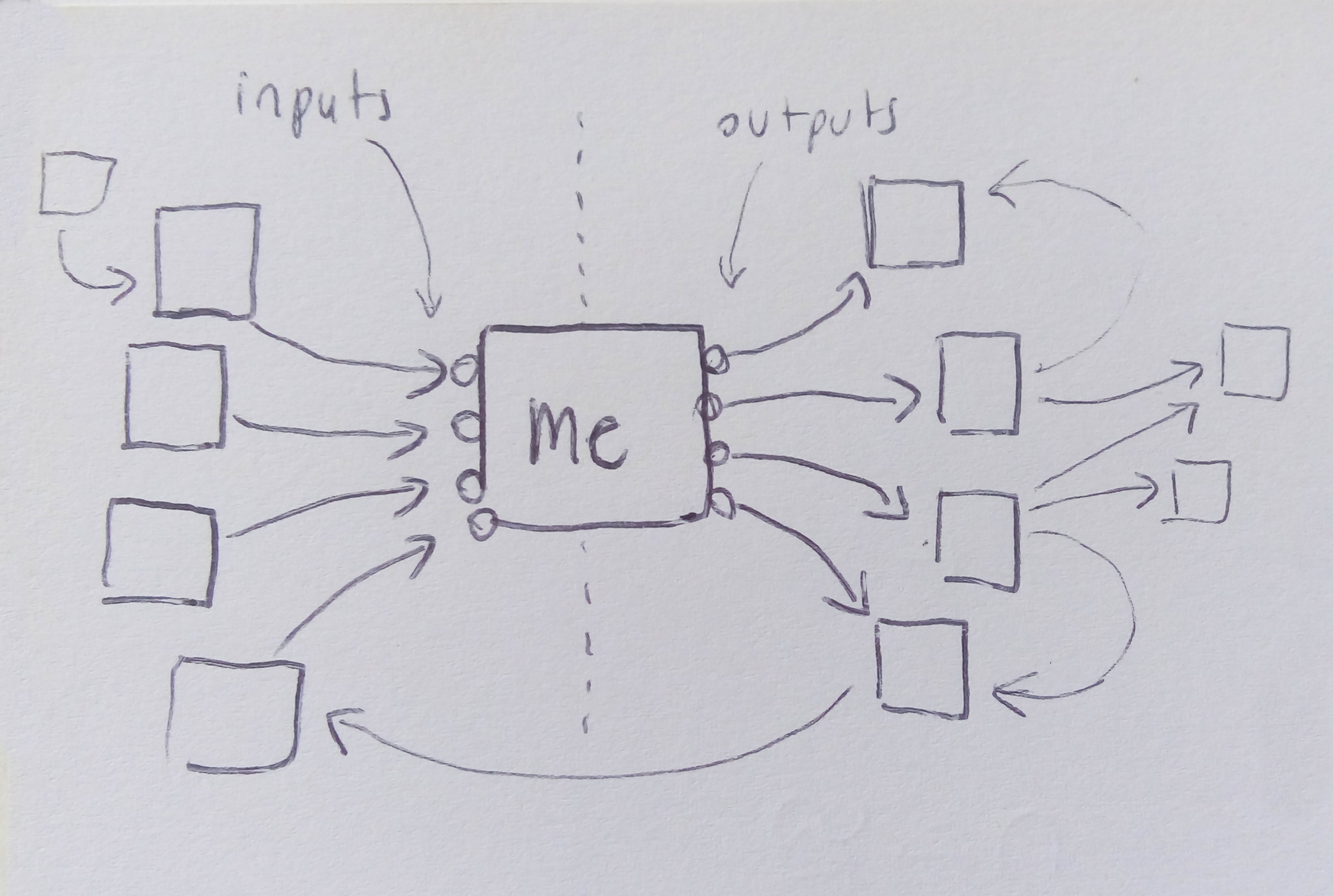 A point-to-point network ends up being the same as a plurality of common bus networks, where each node is master either of his input or his output network.
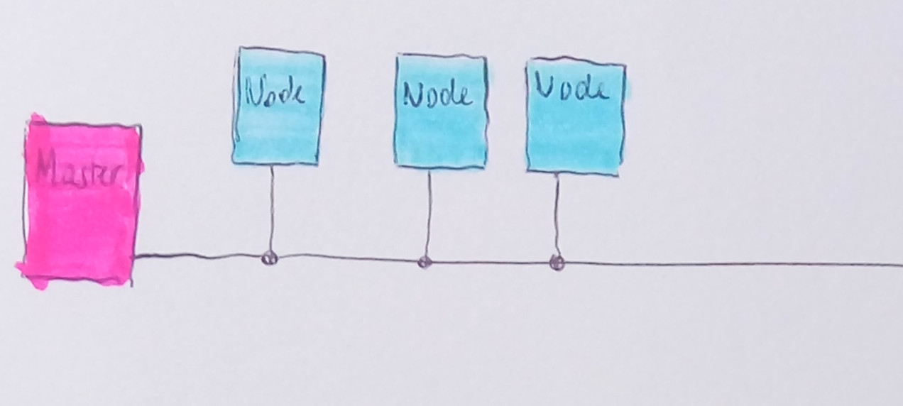
shared bus
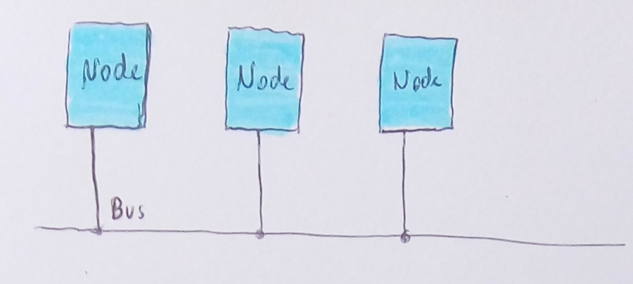 A shared bus network consists of a single bus to which all nodes communicate. Daily life examples for this type of network are spoken conversations between more than two, an internet group chat, and the system in cars that check whether every component is working well.
Two advantages of a shared bus network are the ability to monitor the whole network by monitoring a single wire, and the possibility of optimizing the flow of events for lower latency. There are two drawbacks: one is that each node gets a portion of the bandwidth that is in inverse proportion to the amount of nodes in the network (whereas for the case of distributed, each network has a different bandwidth). The other drawback is that we loose the physical interaction of plugging and unplugging terminals manually.
I2c
Was a good candidate; it was tested by making a random pattern generator that outputs midi. To try that the bandwidth of the network is enough, I sent 24 clocks per step to the random step generator, and evaluated how much stutter and how much the common bus gets saturated from this. The conclusion was that one module can clock the other module with rates as high as 100 clocks per step, for a musical speed of 120 BPM without any noticeable stutter or latency. The problem was that 24 clocks per quarter note were already occupying the bus for most of the time; and so I couldn't expect to be able to connect many more modules to the bus and have them sending too much information to the others. I2C would pose a low limit on the amount of modules that can be integrated to the network, and would put a low limit on how much information these modules could share. Other big problem with I2c is that there is no slave to slave communication. All data transfer needs to be actively mediated by the master, which introduces double processor use and double overhead on most device communications. To solve this, each module would need to have two active Wire objects, and operate as a point-to-point network.
Common Rs232 bus
RS484 is not a protocol in itself, but a standard, meaning that within this standard there are many different networking options. Most of these options are described here (https://users.ece.cmu.edu/~koopman/protsrvy/protsrvy.html). This standard suggested me that maybe I could use the Rs232 terminals in such a way, that would allow using Rs232 for a common bus protocol. This protocol could then be easily translated into the Rs484 standard if needed.
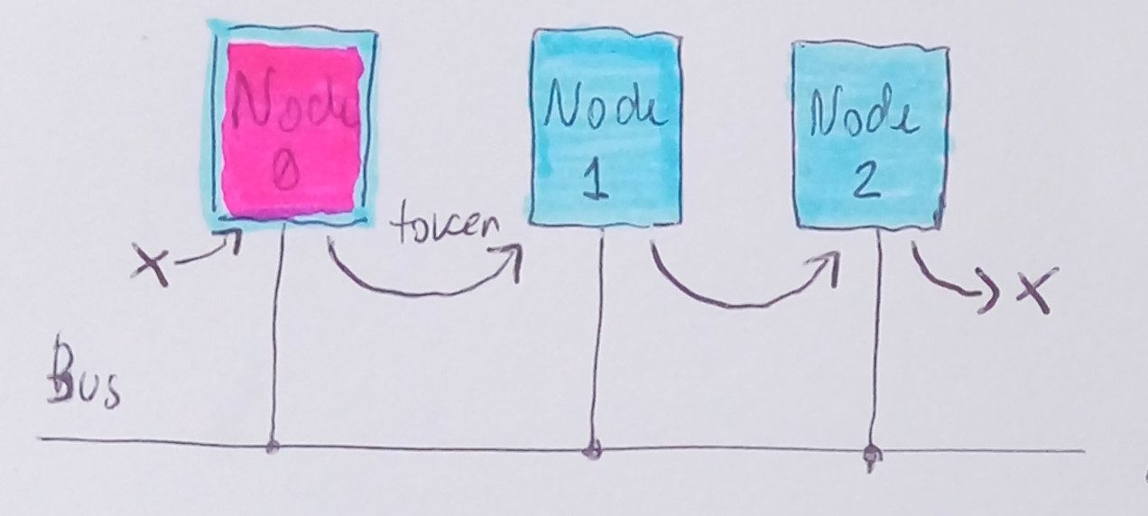
I set out to create this protocol, which I will name TBHN. The concept is the same as in a token ring, only that in this case, there is a token line, and to there is a module in charge of restarting the token every time it reaches the end.
This should allow us to make such a network that:
- Any node can broadcast information to all the other nodes directly.
- Define automatically a Master, or not have a Master at all.
To achieve this, the approach is a hybrid between Token ring and master-bus polling. Token is a signal that is passed from one node to another, sequentially. The concept requires that there is only one token running for the network.
Nodes
- Each node has a token input (TIP) pin and a token output (TOP) pin (later a single pin can fulfill both functions (TP)). Also a common bus pin named COM.
States
- Each module has three states: Listening, Broadcasting and Connecting.
- On Listening state any normal node is on high impedance mode, reading the serial. On Listening state, the node is also reading the TIP pin. If TIP pin is set to 1, it switches to Broadcasting state.
- on Broadcasting state, the node sends all his available information if any, otherwise a "no information" header. Finishing this, it turns the TOP pin to 1, causing the following node in line to switch into Broadcasting state.
- when receiving any data, a node turns the TOP back to 0 if it was set to 1.
- every node has a unique ID, starting from 0. The node number 0 has a special role.
- When a node has just been powered up, it will be set to Connecting state. On connecting state, the node has no address, and has the TOP on state 0. It is listening to all the broadcasts, and keeps track of the highest address in the network. When it's own TIP goes high, it sets his own address to the highest + 1, writes a connected message to the bus, and sets his TOP to 1. This should cause a chain reaction where all the modules assign their addresses incrementally, if powered all at once.
- The TIP is pulled to the state 1, causing the first in line to start the chain reaction from 0. When a node is on Connecting mode, if it detects 1 on its TIP, and has not registered any address, it means that there is no lower module. It will set it's own address to 0. Maybe it is convenient if it waits about 10 bytes before doing so, in case the network is on some weird stuck state.
Token logic and the node 0
- Node number 0 has the role of originating a new token when the token has reached the last module in the token line. It reads the end of the token line when there is a message with disconnected header; or in other words, a timeout.
- last node could detect nothing connected and notify that to the node zero so it doesnmt have to wait for timeout.
Messages
- a message consists of the following components:
- origin is a byte representing a unique identifier that indicates what module has broadcasted that message.
- header is a byte that indicates the mode of the upcoming data. It is divided in two nibbles: first nibble indicates the mode of the message (broadcasted, addressed, empty, offline). The second nibble indicates the length of the upcoming message in words. The maximum message length is 16*4 bytes. Maybe if the second nibble is F, the listeners will wait for a special termination byte.
- an offline header is equivalent to a disconnected module. The idea is that a module that is offline or not connected, will generate an offline header by not sending anything. You can also think of this as a timeout of the length of a single byte.
practicalities
connection
-----\         /---------------\         /---------------\         /---------->
      \       /                 \       /                 \       /
    |-TI-----TO---|           |-TI-----TO---|           |-TI-----TO---|
    |    node     |           |    node     |           |    node     |
    |-----COM-----|           |-----COM-----|           |-----COM-----|
           |                         |                         |
-----------|-----------bus-----------|-------------------------|-------------->


<-- "left or previous"  "right or next"-->
TI is input with internal pull-up, and the logic is direct (not inverse) meaning that it defaults to 1
For easier commenting, in the code, modules are said to be on the left or right. This corresponds to the hierarchical connection of the ti/to. A module on the left is the one whose TOP is connected to the node's TIP in question. A node on the right, (also refered as the next node) is the one whose TIP is connected to the node's TOP in question.
TBHN should allow theoretically 100 messages per second, from each module in a network where there are three modules. In that case, the latency "downstream" is very low, and "upstream" is ~10ms. There is a chance I can implement a "end of line message" where the last node detects no following node, and communicates this to the bus, making the master react instantly without waiting a timeout.
Development
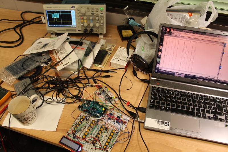 Three devices in the network broadcasting messages, that were also sent to the laptop's serial port.
To develop the protocol, I needed to follow incremental steps. Otherwise it becomes too difficult to spot the source of a problem.
step 1: common bus working
Set up three arduinos, all connected to the same bus. Test that it is possible to address each individual arduino in the network by a hard coded address, and that the arduino can respond with his own ID plus a string. This is proves that there is a network, and there can be communications through it.
step 2: Automatic address assignation
The arduinos are tied with the TI and TO connections. One single arduino is set to reflect in the serial all the signals that happen in the common bus. After the automatic address assignation, the arduino that is connected to the serial should be able to address individually each arduino as in the previous step
step 3: Automatic token
The arduinos should start their activity without input from the node that is connected to the serial. The message length is fixed. The activity can be seen in the serial output of one of the nodes.
- The testing at this stage showed that I can send 43.5 messages of 8 bytes per second (the Fq of the TOP of one device was 14.5 Hz, and there were three devices on the bus)
- The payload is 6 bytes.
- The bus shows that there is room for duplicating the message rate, and if I can also get it working at higher baud rates, I could get some extra room aswell.
- message rate should be enough to connect enough modules if only one is going to be sending a 12 ppqn clock.
step 4: A node can be added or removed without compromising the network
This effect was granted automatically, because the continuity is given by the physical cable between nodes, thus removing a node becomes a complete removal from the network. Anyhow, there was a bug where newly connected nodes would assume an address 0 instantly and started creating new tokens that destroyed the network reliability. This bug seems to happen in many different cases, and they are being found and addressed one by one.
step 5: Message length is defined in the header
step 6: Pack the protocol into a library
step 7: Messages with undefined length, finished with a message terminator
One change that I discovered that I should make to the protocol, is that the header byte goes before and not after the origin byte. This reduces the bandwidth usage, because in case of sending a "nothing to send" header, the origin byte becomes redundant. This change of order also theoretically allows each node to host multiple virtual nodes that could be addressed by the network.
Further development ideas
- The protocol should support a closed token loop somehow. It would remove the token timeout wait at the end of each round, potentially triplicating the frequency of communication. Mabe the token timeout could smaller aswell.
- When a module detects that a message has been sent and has a token, it should release his token. This would prevent overlapping of messages in case a device took too long to answer to the token causing a token restart.
- The current prototype at this time uses two Arduino libraries: hardware serial, and SendOnlySoftwareSerial. It constructs and destroys each of these serial ports, to share one single pin that is connected to the network. I am sure that this approach leads to big processing overheads in the MCU, but it alleviates a big overhead in development time.
- The last node should have a way to detect that there is no following node, and send a special byte signal to the bus. This would notify the node zero, and it would no longer need to wait a timeout to restart the token.