modular sequencing digital prototype
how could I design a pattern and melody sequencer in such a way that allows the user to make his own sequence systems?
This is the process of prototyping digitally the modular pattern system maker tool. It was an exploration done to determine the kind of hardware that would be most interesting to prototype physically, in the context of my thesis project.
Please visit the question and expand on system.
The idea of a system maker is that, from many instances of the same element, a new system can be created, that will manifest qualities not present in any of it's component. The user becomes the designer of the music composition system. This product comprised of this set of elements is what I will call the builder. By using the builder, the user can create his own music composition system. Ideally, this builder would allow the creation of music generation systems as well.
Molecular behaviour
The molecular behaviour is what I explored when I made Licog composer, and it manifested some interesting emergent features. Nevertheless, a hardware version of such a device could be too expensive due to the quantity of required copies of the component, and the difficulties that pose connecting many hardware elements together. (see Brocs)
extrapolation
A nice feature to add to this experiment that I still have due to do, is to enable multiplayer, interactive composition. If I rebuild this prototype in a web browser, and communicate the client browsers through a socket, it could become an interesting collaborative composition toy.
Other interesting feature to this platform would be the ability to enclose groups of nodes as a single node that would have some inputs and outputs. This would enable the player to build on a higher level basis, in the same ways that occurs on puredata. For this feature, there is the added complexity and interaction challenge of making the notes within a system, somehow parametric (because it is not very desirable that a group of these nodes would have a fixed harmonic structure or set of timbres).
The third, and obvious feature that I can think of here, is that one node should be able to introduce changes over the global parameters. One node should be able to change timbre parameters of an instrument, to change the tempo, etc. One node should also be able to capture sound and reproduce it, as it was speculated for the brocs project.
Grid based behaviour
The idea of the grid based behaviour is to make a hybrid between a molecular behaved system maker and traditional sequencers. This is due to the fact that sequencers can generate complete patterns using a single piece of hardware. In this exploration I intend to add modular features to a basic sequencer, obtaining a sequencer platform.
An example of a grid based modular system, are the analogue sequencers; because we can use their outputs as inputs, and, for example, connect another sequencer's clock input to a gate output of the sequencer.
Javascript prototyping base
I designed and programmed a basic modular patching script in JavaScript. It defines a module that can be instanced multiple times. It contains a layer on top that defines it's behaviours such as interaction, response to messages, user defined behaviour options, etc.
The most basic behaviour of a sequencer is the following:
- upon a clock tick, advance a playhead one step.
- If the playhead position reaches the last step, the following step will be the first (0)
- when the playhead position changes, all the sequenced events will be sent
Basic sequencer behaviour
The first component design was a four step, four events sequencer. This means that the playhead goes back to zero every four steps, and there are only four possible events that can be programmed. The four steps and four events could be programmed by clicking any of the 16 virtual buttons arranged in a 4*4 grid. All the sequencers play header was synced to a single master transport (i.e. metronome)
Step jumping or event remap
The first additional feature to this bare minimum sequencer, was the possibility to obey another sequencer's input instead of the master clock, and jump to any step provided by the input instead of incrementing 1 step per event. I chose this feature, because it results in a mapping matrix: if a sequencer sends a [0,1,2,3] sequence, the child sequencer (the other sequencer that is receiving the signals) would play as a normal sequencer, but any other sequence such as [3,1,2,1] will repeat a step from the child sequencer whilst the primary sequencer is playing linearly. In this way, the horizontal axis of the child sequencer becomes an input, and the vertical becomes an output. An usage example of this feature (if there were more available events, and more available steps) would be, to create a palette of notes in a scale that are sequenced by the parent sequencer. Or perhaps, a palette of chords. It already presents us with an improvement over the traditional sequencing approach because, if we want to change the harmony of a melody, instead of needing to reprogram every note on each step, we can now just change one event per grade. This approach also allows complete transformations to a melody, if for example we start mapping all the child sequencer events to a same note, while the parent sequencer is playing a sequence with many distinct notes, and then start adding tonal variations, thus obtaining a very original melodic progression for the ambit of live electronic music.

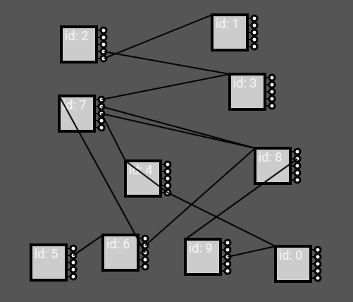
Multi output
The second introduced feature to the sequencer, was to address each possible sequencer value (vertical axis) to a different output. This will allow us to generate alternating outputs to one single sequencer event. In the following example, the point of view is taken from the leftmost sequencer, which is the only clock synced sequencer. The resulting melody of the system will be a repetition of [1,2,3,x], and x will be a number that alternates between [0,1,2,3] as an example. The resulting pattern was programmed in 12 steps and is 16 steps long: [0,1,2,0,0,1,2,1,0,1,2,2,0,1,2,3].
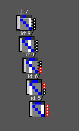
Clock ambiguity
An interesting problem is that some behaviours may be different depending whether the connection goes "up an id" or "down an id". The system scans each one of the modules, in the order that is indicated by each module's id. If we set each module to respond instantly to any signal, there is no big difference on the response regardless of whether the connection goes up or down id's. But if we set the modules to wait for a clock step to respond, there will be a difference. If a connection goes up an id, upon clock tick, the module will have already received the signal to which it has to respond, from it's parent. If the connection goes down an id, when the clock ticks, the parent would have not yet sent the signal to which the sequencer has to respond, and therefore, it will respond to the signal with the delay of one whole clock tick.
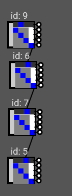
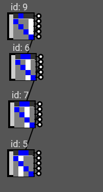
In the left: instant response generates tiny difference regarding response up and down id's. In the right, when elements are clock bound, down-id connected elements will be always one clock behind.
If this was a hardware situation, there would be no clear rule, because the elements would not be updated progressively as in the computer simulation. The result is that instead of a clear rule, whether the response is delayed or not will
Emission delay
Emission delay consists in receiving and reacting instantly to all incoming signals, but buffering all the resulting signals into a buffer, that will be send in the next clock tick.
The problem that results from this solution, is that the delay still happens, but in an even less intuitive way; on the sub-sequent, down-id module if all the chained ones are clock synced. The first module sends a signal to a lower id module; which reacts instantly and queues the output to the next step, that comes right after the signal. It sends it to the next module, and it reacts instantly, but the clock that corresponded to that signal in the upper module, has already happened; meaning that in this, sub-sequent module, the output signal will belong to the next clock.
seem to be random.
Reaction delay
When an element responds to another sequencer's input, and it is quantized to clock steps, it must always buffer it's reaction for the next clock step.
- Upon clock tick, it reacts to the buffered incoming signals
- upon reception, it stores incoming signals in a buffer.
This approach doesn't solve the problem, as the reactions remain ambiguous.
Layered processing
This solution consists on processing all the elements in two separate processes, ion the same way we would treat graphic layers if we wanted to ensure that elements to be drawn from an array, would be drawn in a different order than the one specified by the array. Applied to time, this could ensure that we first process all the incoming signals to the elements, and once all the incoming signals are processed, we proceed to process all the elements reactions to the clock tick. What has been done so far, is that on each clock tick, all the elements are processed, while reactions to signals are processed as soon as the happen. To apply this procedure, each element must now have two signal queues: one queue for the incoming messages, and other queue for the outgoing messages. Upon clock, all outgoing messages are sent, and after clock, all incoming messages are processed, thus generating a new set of outgoing messages.
This solution ends up giving a consistent behaviour of delaying the signal one clock independent of wether the signal is up or down the array. To implement this solution, I had to create an additional property which determines wether a module can trigger itself. Perhaps this property must have been created from the beggining, but the lack of this came clear only in this stage.
The first problem of this solution, is that is impractical to apply on a hardware situation. It would need instead to be replaced by each modules independent timing, consisting on waiting for a clock signal to send, and after sending, processing all the buffered incoming signals. If this is possible, the other problem that I see that some of the programming may become counter intuitive, because as user you may need to take into account a cumulative step displacement backward when programming events. I think that this problem reflects that this system is not intended to be clock synced on any device until the last ones, that will ultimately trigger sounds. In a way it means that processing delays is not a problem altogether, as far as it happens consistently. Processing delay also permits us to produce molecular behaviour.
Simple algorithm
commit bf3f8e1c61
(This part will be rewritten in a clearer redaction later)
The other valid consists in relating self-triggering with clock sync. Seen from another point of view, it seems as if the device should consider the clock as a signal that should generate a trigger instead of using signal inputs as a trigger. This requires that each unit is capable of displaying multiple states on each view, instead of replacing the view at every input. When the device is clock-locked, but it is also receiving signals, it will look as if the device remains stuck at the position zero (if jumping is activated) or that is jumping several steps on each clock (if jumping is not active). But the truth for the first case, is that the device is virtually reacting at the same time to the clock than it's response to the signal, because these two reactions are buffered. This is why the component should be displaying the state of the buffer rather than the state of the last reaction, giving a new, more rich meaning to the current state.
Extrapolation
This experiment was based intentionally on very simple sequencers. If we expanded the capability of each module to the one of any sequencer, there would be many more expressive possibilities than the ones expressed here. For instance, the signal emitted from one sequencer to another could be comprised of many bytes (so far has been single byte messages) in such a way that a static message could be transmitted and routed through many sequencers, where a header byte may change through the patch because it is destined for addressing, while some payload bytes may go through the whole patch untouched until a destination (e.g. synth). The payload message, of course, could be also tweaked through the patching route. This will give us two layers of message processing: one layer which determines the physical route taken by a message, and other layers that determine the effect of this message once it arrives to the final destination. In this way you could consider these as modules that expand a sequencing interface (like in Roli Blocks), and also work with them as modules that expand the capability of the system, as it happens in Eurorack.
Conclusions
This small experiment validates the idea of making a modular sequencer as a hybrid between molecular and sequencer behaviours. It also presented some of the first nuanced challenges that modularizing sequencers will present on prototyping, and gives hints to their solutions. This experiment is also a good preparation that will make clearer what are the features that a module will need, and what features are not important for a module.
One of the important questions that remain, is the factor of shape and size: where the physical unit should stand between an inexpensive, naked circuit, or a manufactured, high end piece of hardware. I know that none of both ends is a correct answer. A naked circuit lacks the appeal of a live performance (hopefully the system can communicate that the patterns are being generated on stage). A high end piece of hardware discourages having many copies of the same unit, and so discourages making complex systems that involve many components.
As designer I would like to depart a bit from the shape factor of the sequencer; just to express the idea that (albeit based on), it is a different and new mean of pattern composition. However, I wouldn't trade the convenience of this shape factor just to express this idea; so the fact of changing the shape depends on whether I can find a new shape factor that is as convenient as the 16 button matrix format.
If clock should be bang based, this means that in the same fashion as in Puredata a clock triggers events, it's message should be a number that each module could also follow for absolute sync. In an absolute sync mode, the incremental mode can both be incrementing from zero, or synced to the modulus of this absolute clock. In this way, two parallel sequences can be guaranteed to be in the same phase.
There is a need for sequence chaining and reset. One sequence should be able to start a next sequencer as if they were the extension. A sequencer should be able to reset other sequencer position to the start position as well; because these approaches are simpler and more friendly to a newcomer.