polar sequencer
General idea
This is a project for the introduction to dataflow programming course. I took the approach of sensing real world variables to make music from those. As the topic is free, with the only condition of ending up with something that works and is appealing by the use of Puredata; I went towards an idea that could potentially become a creative tool, despite that within the context of the course, I didn't manage to fulfill that potential, but just to display it as a possibility.
The original idea was to make a sort of augmented drawing paper; in which the user's input is drawing and the output is music (and of course, the drawing itself). Intuitively, and in the core of this idea, was to represent the musical loop in the paper as a polar diagram; in the same fashion as the data is present in vinyls and cd's. There is other precedent in old music boxes which had their musical patterns etched in a metallic disc that rotated. In general, the idea that a musical loop is represented in a polar diagram is mainstream and seems intuitively understandable.
In order to achieve the minimum; the plan was to develop the artificial vision algorhythm in processing, because there was less than a week time to develop it; and for the hardest part, would be the fastest option. Processing also is more efficient for pixel processing. From the image readout there would be and OSC message output, that would converted to sound in the same fashion as MIDI messages.
Cartesian to polar camera readout
I first tried to apply the trigonometric functions that I are for drawing to address polar points from the video, and display those points in Cartesian positions. First I couldn't manage to get it well mapped, and there was no way to check where I was making mistakes. So I made a test sketch that would draw dots based on the cartesian function I was aiming for. The mistakes became clear, and I came up with the following code:
  void setup() {
    size(640, 480);
  }

  void draw() {
    int rpx=0;//reading pointer coordinates, dor the polar conversion
    int rpy=0;
    int index = 0;
    for (int y = 0; y < height; y++) {
      for (int x = 0; x < width; x++) {
        rpx=(width/2)+int(cos(x/float(width)\*TWO\_PI)\*y);
        rpy=(height/2)+int(sin(x/float(width)\*TWO\_PI)\*y);
        fill(0);
        stroke(0);
        point(width/2,height/2);
        point(rpx,rpy);
        index++;
      }
    }

  }
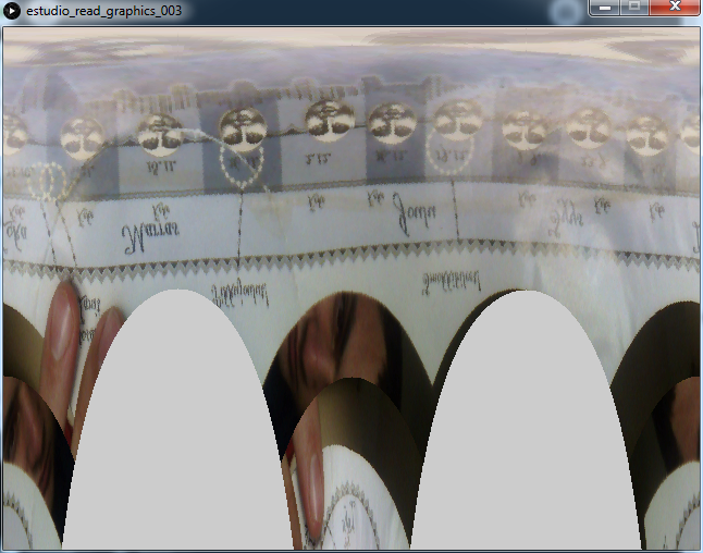
And it's result: 
These pixels will be the points that are read in the video input and sorted in the pixel matrix. The final code that converts polar to cartesian makes a loop throughout each screen pixel, calculates which is the video pixel from where to take it's colour and applies it. Note that the pixels array is not bidimensional as to access them by x,y coordinates. Instead one can calculate the 1d array pixel from coordinates by using the
i=x+(y\*width)
where i is the index, and x & y, the corresponding coordinates.
I could have taken the approach of reading the image directly in its polar disposition, but I assumed that the conversion would make a better match between the computer graphic process and the intuition of drawing circles.
/*
track darker parts with the intention of reading
*/
import processing.video.\*;

Capture video;

void setup() {
    size(640, 480);
    // Uses the default video input, see the reference if this causes an error
    video = new Capture(this, width, height);
    video.start();
    noStroke();
    smooth();
}

int treshold = 90;

void draw() {
    loadPixels();
    int rpx = 0; //reading pointer coordinates, dor the polar conversion
    int rpy = 0;
    int polarindex = 0;
    if (video.available()) {
        video.read();

        video.loadPixels();
        int index = 0;

        for (int y = 0; y < video.height; y++) {
            for (int x = 0; x < video.width; x++) {
                int pixelValue = pixels\[index\];

                //get the pixel from a polar coordinate of the video
                rrpx = (width / 2) + int(cos(x / float(width)\ * TWO_PI)\ * y);
                rpy = (height / 2) + int(sin(x / float(width)\ * TWO_PI)\ * y);
                ill(0);
                //point(width/2,height/2);
                //point(rpx,rpy);

                polarindex = rpx + (rpy\ * width);
                if (polarindex < pixels.length && polarindex > 0)
                    pixels\[index\] = video.pixels\[polarindex\];
                //analyze whether there is a sequenced note
                float pixelBrightness = brightness(pixelValue);
                if (pixelBrightness < treshold) {


                }
                index++;
            }
        }

        updatePixels();
    }
}
blob detection
There is a plugin intended for blob detection. The blob objects are created every draw cycle; which means that each blob doesn't persist but is created again each time; and a specially big problem is that each blob changes it's index number if any upper blob appears or dissapears. Several attempts of persisting blobs were made. These ranged from the idea of creating a new object for each blob, and then an algorhythms that would administrate the creation and deletion of these persistent objects according to the blobs, to completely creating from scratch, a new algorythm that would detect marked blocks with the purpose of using them for the sequencer
[caption id="attachment_909" align="alignnone" width="641"]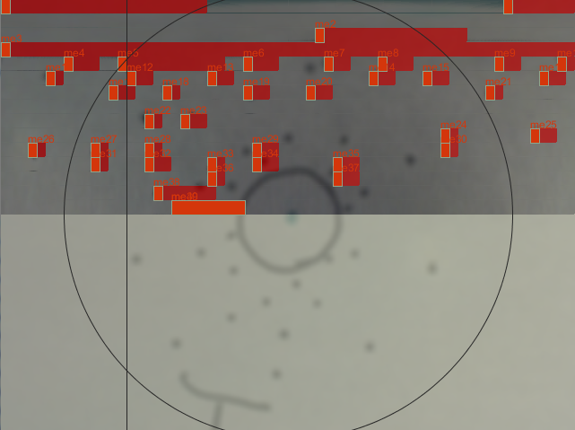 An attempt of treshold-based readout of polar events. The red squares are the interpreted sequencer events whereas the image in the background is the actual drawing.[/caption]
The solution to the persistence problem
The approach that worked best, was to generate ephimeral objects associated to eac blob, that would exist and persist only while the player cursor was over that event.
I made a very simple algorhythm to check whether the current blob under the cursor already has an associated object. To understand better, we have a bar that sweeps the screen repeatedly, with an horizontal movement; reading at each step, one column. By reading we mean that it loops for each x pixel in it; vertically. The variable that stores the reading position was named stepheader; and it advances one unit each step.
line(stepheader*stepw, 0, stepheader*stepw, height); stepheader+=1; stepheader=stepheader%steps;
Then, when blobs are read, each blob checks wether it is "under" the stepheader position. In the code, b is each isntance of a blob. This code is extracted from a loop that goes through every availiable Blob[] instance.
if ((b.xMin < stepn) && (b.xMax > stepn)) {
    //if the blob is inside the reading header

    //get sound event vars
    int tdiv = floor(b.y\ * divs); //divs is the n° of rows to be interpreted as tones. it's quantized to make tones more manageable to the user.
    float tstp = b.x\ * steps;
    float tlen = b.w\ * stepw;
    float tsz = b.h\ * height;
    if (!isOccupied(tdiv))
        sounds\[tdiv\] = new sound(tstp, tdiv, tlen, tsz);
    stroke(colors\[2\]);
    fill(colors\[2\]);
} else {
    noFill();
    stroke(colors\[3\]);
}
Now, for the solution I stored each sound object, which are the persistent copies of the blobs, in an array that has the same amount of spaces than the program has divs. Whenever a sound object is generated, it is overwriting any other sound event that could be in the same tone. The function isOccupied(int div), returns true if in the checked div (int div) there is already a sound object.
The other part of this solution to work, was to make the sounds to be ephimeral: when they are created, they have a lifespan, and get deleted upon completion of this time. The lifespan of the sound object is related to the width of the blob, as in the sequencer, the horizontal axis represents the time. Upon it's creation, the event has a defined dissapearing time, and there is only one OSC message, which contains the duration, instead of having note on/note off events, as attempted first.
osc communications
The OSC communications are built-in Puredata, and have a library for processing; which makes its usage straightforward. After fiddling around with it, I chose a simple approach here aswell, which was assigning one synth voice to some of the possible tones. The data string was written as follows:
OscMessage mensaje1 = new OscMessage("/stt");
mensaje1.add(dst);// id
mensaje1.add(dst+15);// note
mensaje1.add(l+15);// duration
mensaje1.add(size);// velocity
oscP5.send(mensaje1, direccionRemota);
Download the radial sequencer 1.012 processing patch. It requires the Processing's Video, Schlegel's Oscp5 and v3ga's Blob detection libraries.
polyphonic synth
Despite being the task to display knowledge on Puredata, the Synth ended up being simple; and not very impressive in terms of sound quality. The poliphony is achieved by using an abstraction of a synth, that is instanced multiple times, for each voice.
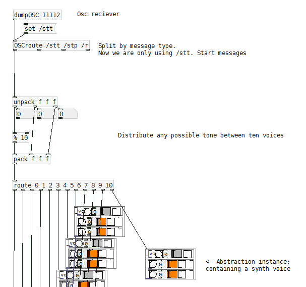
This way of distributing voices has the defect of arbitrarily overwriting voices; where a round-robin method would have been the optimal. But as in this case, we are working with a defined and limited number of possible tones, this method serves the purpose. For future development, the best option will be to use a poly object, and optimize the OSC message to fit this object's conditions, or either remake this poly object to fit my current OSC communication protocol.
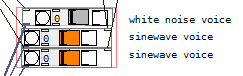
sound diversity
I expected to generate a variety of timbres depending on the distance of the event from the circle's center; and in a future by the event's color. As the objects in the center of the circle have less positional precision (because they are bigger when converted to cartesian), and therefore, less time precision, I wanted to make these tones bassier and with slower attack, while the the events in higher notes, to have more white noise and faster attack, as to imitate the cymbals and snare sounds. This was not completely achieved, but in part; by using two transposed sinewaves and a white noise generator for each synth voice.
Each one of these had it's own envelope (consisting only of an attack and delay) and tone; that were defined by the OSC input. The tone defines not only the oscillator pitches, but also, as I mentioned above, their attacks and amount of white noise. Because of the time I couldn't define the best values for the volume and envelope functions, as to give a clear and satisfactory result.
Download puredata radial sequencer synth 1.03